If I understand correctly Lender configuration is a simplified version of the added emitter follower between LTP and driver of VAS. It gives more accurate V-to-I conversion from input to voltage amplification stage. Double CCS current drive VAS with emitter follower arrange was used in Revox B285/286 as well from 80's. Its sound was spotless.
See the protective diode and the 2.7 kOhm level shift resistor ?
If I understand correctly Lender configuration is a simplified version of the added emitter follower between LTP and driver of VAS. It gives more accurate V-to-I conversion from input to voltage amplification stage. Double CCS current drive VAS with emitter follower arrange was used in Revox B285/286 as well from 80's. Its sound was spotless.
This Revox looks interesting. I actually have some SK170 Jfets available 🙂
It is necessary to make a powerful output stage. At least 3 pairs, preferably 4 pairs of high-power output transistors.it doesn't matter if it's laterals, Bipolars ,or MOSFETs.
Yeah, in the real build I would use 2 pairs (or dual die LatFets). But for the simulation this doesn't matter, right?
Here is my latest sim.
1) Zener changed to 20V to lower power dissipation on the LTP cascode.
2) CCS changed to BD139
3) current mirror resistors kept at 470 Ohm
4) feedback cap at 10pF - optimized for square wave response
5) Slew Rate 40V/us (Vpp at 48V)
6) in this asc file, gain is set too high - just to be able to get bigger swing to measure SR
I'm sure there is still way for improvement, Maxim - do not order PCBs just yet 🙂
Attachments
Last edited:
Уes.😱Yeah, in the real build I would use 2 pairs (or dual die LatFets). But for the simulation this doesn't matter, right?
BTW - is this OK to bias both cascodes from the same Zener, like I did in my sim?
Or each cascode should have it's own Zener?
Or each cascode should have it's own Zener?
Here is my latest sim.
1) Zener changed to 20V to lower power dissipation on the LTP cascode.
2) CCS changed to BD139
3) current mirror resistors kept at 470 Ohm
5) feedback cap at 10pF - optimized for square wave response
6) Slew Rate 40V/us (Vpp at 48V)
7) in this asc file, gain is set too high - just to be able to get bigger swing to measure SR
I'm sure there is still way for improvement, Maxim - do not order PCBs just yet 🙂
Where is the resistor between the Q12 and Q8 bases ? The denouement must be done !let 10 ohms, but it should stand
Here is my latest sim.
1) Zener changed to 20V to lower power dissipation on the LTP cascode.
2) CCS changed to BD139
3) current mirror resistors kept at 470 Ohm
4) feedback cap at 10pF - optimized for square wave response
5) Slew Rate 40V/us (Vpp at 48V)
6) in this asc file, gain is set too high - just to be able to get bigger swing to measure SR
I'm sure there is still way for improvement, Maxim - do not order PCBs just yet 🙂
The model tolerates.And in iron it is better to be safe
Will have to try 20kHz sine tests, and then the clip tests.
Also, over the weekend, will try the Revox voltage shifter/buffer, to see how it performs....
Then - version with JFETs in the input might be interesting.
Otherwise have no use for these SK170 devices I have hoarded..
Also, over the weekend, will try the Revox voltage shifter/buffer, to see how it performs....
Then - version with JFETs in the input might be interesting.
Otherwise have no use for these SK170 devices I have hoarded..
Last edited:
This Revox amp must have low-voltage rails, if one BC327 (Q109) transistor can take both rails voltage and survive...
And all these visible transistors are small BC type, not even one TO-126.
This must be 20W amp...
And all these visible transistors are small BC type, not even one TO-126.
This must be 20W amp...
😀😀😀This Revox amp must have low-voltage rails, if one BC327 (Q109) transistor can take both rails voltage and survive...
And all these visible transistors are small BC type, not even one TO-126.
This must be 20W amp...
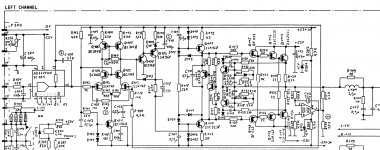
Nope, here is actual schematic, differs from Egra's.
Rails are 50V, but transistors are different.. Must be 'premium' model.
Update: well, this is not original Revox schematic I guess. No idea where did I get it from...
But it looks like people like it, to re-do it with modern devices and higher power...
Rails are 50V, but transistors are different.. Must be 'premium' model.
Update: well, this is not original Revox schematic I guess. No idea where did I get it from...
But it looks like people like it, to re-do it with modern devices and higher power...
Attachments
Last edited:
>R123 4.7K against 2,7 K!
This is not original Revox, we can't trust it....
It's a upgraded, modernized version from Brazil...
Who knows if this was even ever built...
This is not original Revox, we can't trust it....
It's a upgraded, modernized version from Brazil...
Who knows if this was even ever built...
>R123 4.7K against 2,7 K!
This is not original Revox, we can't trust it....
It's a upgraded, modernized version from Brazil...
Who knows if this was even ever built...
I noticed that even here colleagues often neglect safe modes
Found service manual for real Revox 285.
Different transistors. Rails 52V
I guess original printout did not show transistor types or values, and someone added it manually.
Luckily, Q109 is not BC327 🙂
Different transistors. Rails 52V
I guess original printout did not show transistor types or values, and someone added it manually.
Luckily, Q109 is not BC327 🙂
Attachments
Last edited:
- Home
- Amplifiers
- Solid State
- Unusual amp from 1987