YeSo soon??? 🙂
I assumed. The safe operation area of the amplifier is not disturbed . Well, maybe check the correction again .
A fresh look would be from the outside .Maybe we don't notice the error . Or maybe there isn't a mistake .
>I'll show you the DC analysis .in two variants.With equal power across the cascode transistors and an alternative
I'm not worried about cascode...
I'm worried about power dissipation in input LTP + CCS. It's too high, at least with 45V rails.
Slew Rate in version with your LTP/CCS (high power dissipation) is higher (26V/us) than with my LTP/CCS (15V/us).
I'm not worried about cascode...
I'm worried about power dissipation in input LTP + CCS. It's too high, at least with 45V rails.
Slew Rate in version with your LTP/CCS (high power dissipation) is higher (26V/us) than with my LTP/CCS (15V/us).
Last edited:
The meander is excellent. Maybe you have an inaccuracy in the conversion to digital readings ?So soon??? 🙂
We need higher slew rate. The 1st sim I published yesterday, had SR=50V/us.
Now my latest sim is back to 15V/us
We can't have all small transistor in input LTP running hot at 100mW-250mW, on the other hand - with lower
dissipation, RS goes down...
And there's a cascode>I'll show you the DC analysis .in two variants.With equal power across the cascode transistors and an alternative
I'm not worried about cascode...
I'm worried about power dissipation in input LTP + CCS. It's too high, at least with 45V rails.
Slew Rate in version with your LTP/CCS (high power dissipation) is higher (26V/us) than with my LTP/CCS (15V/us).
In the input?
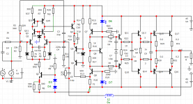
I thought in the input stage we have:
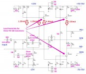
a) 1 pair of LTP tranistors (Q1/Q3) - running hot (120mW each)
b) current mirror (Q18/Q19) (very small power dissipation, they are OK)
c) CCS (Current Source) (Q2) - running hot (222mW)
In the voltage shifter/buffer:
Q4/Q5/Q6 - each running over 150mW, so TO-126 needed here anyway. Not worried about them.
They need to drop almost 90V, so they have to dissipate heat, no way around it.
I'm worried about a) and b)
Can't have more then 80mW per small transistor; they gonna be too hot otherwise..
Preferably way less then 80mW.
I thought in the input stage we have:
a) 1 pair of LTP tranistors (Q1/Q3) - running hot (120mW each)
b) current mirror (Q18/Q19) (very small power dissipation, they are OK)
c) CCS (Current Source) (Q2) - running hot (222mW)
In the voltage shifter/buffer:
Q4/Q5/Q6 - each running over 150mW, so TO-126 needed here anyway. Not worried about them.
They need to drop almost 90V, so they have to dissipate heat, no way around it.
I'm worried about a) and b)
Can't have more then 80mW per small transistor; they gonna be too hot otherwise..
Preferably way less then 80mW.
Last edited:
>I'll show you the DC analysis .in two variants.With equal power across the cascode transistors and an alternative
I'm not worried about cascode...
I'm worried about power dissipation in input LTP + CCS. It's too high, at least with 45V rails.
Slew Rate in version with your LTP/CCS (high power dissipation) is higher (26V/us) than with my LTP/CCS (15V/us).
КаскодIn the input?
I thought in the input stage we have:
a) 1 pair of LTP tranistors (Q1/Q3) - running hot (120mW each)
b) current mirror (Q18/Q19) (very small power dissipation, they are OK)
c) CCS (Current Source) (Q2) - running hot (222mW)
TRfcrjl
In the voltage shifter/buffer:
Q4/Q5/Q6 - each running over 150mW, so TO-126 needed here anyway. Not worried about them.
They need to drop almost 90V, so they have to dissipate heat, no way around it.
I'm worried about a) and b)
Can't have more then 80mW per small transistor; they gonna be too hot otherwise..
Preferably way less then 80mW.
Attachments
We can cascode it like this, distortions look even better.
But I hope 1.2mA LTP can be improved for higher SR, without extra cascode.
But I hope 1.2mA LTP can be improved for higher SR, without extra cascode.
Attachments
Last edited:
Ha! We posted same thing at the same minute 🙂
And the CCS can be TO-126, no problems here...
And the CCS can be TO-126, no problems here...
Last edited:
I have a resistor between the current source and the differential stage. Additionally.Its selection can reduce the heating of the current source transistor
Plus, we can use electrolytic capacitors at the input by applying a polarizing voltage to them from the collector of the current source.
Plus, we can use electrolytic capacitors at the input by applying a polarizing voltage to them from the collector of the current source.
Last edited:
A 100-300ohm resistor is needed between q12 and Q8 . Just a denouement
How much stability do we have at 0dB ?
How much stability do we have at 0dB ?
So soon??? 🙂
We need higher slew rate. The 1st sim I published yesterday, had SR=50V/us.
Now my latest sim is back to 15V/us
We can't have all small transistor in input LTP running hot at 100mW-250mW, on the other hand - with lower
dissipation, RS goes down...
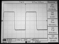
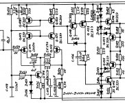
@ Minek. Valery uses simple driver between LTP and VAS, set in Lender configuration. LTPs run 1.35 mA, SR 50V/us. Rise time 20kHz - 800ns (measured)
Attachments
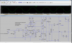
Egra, I was doing sims of Vhex amp.
Results were inconsistent with Valery's numbers.
Sim it yourself..
Maybe Vhex measures better then it sims....
Perhaps I should revisit these sims, but I remember distortions were too high..
Update: I just re-run square waves on Vhex - 20V/us - just little bit better then LMK and Wiederhold, and
Thd is much higher....
Update2: Of course we can compromise - if someone doesn't care about having perfect square waves, there is a way to make Wiederhold or LMK faster too....
After all, nobody listens to square waves 🙂
Or even sinus waves, far that matter..
Apparently my sim results differ from Vhex screenshots....
Last edited:
What exactly do you mean?
In the clip, you need to see the modes of the Q15 transistor with a common emitter .I'm afraid that's not very good.
Last edited:
@ Maxim. Lender configuration ensures a better phase response than a "regular" common-emitter driver
>Result was very "mediocre". Real world measurements are light years better.
Usually the opposite is true...
Good thing - Vhex runs input stage from 15V rails - that would help - no need for cascoding.
Usually the opposite is true...
Good thing - Vhex runs input stage from 15V rails - that would help - no need for cascoding.
If I understand correctly Lender configuration is a simplified version of the added emitter follower between LTP and driver of VAS. It gives more accurate V-to-I conversion from input to voltage amplification stage. Double CCS current drive VAS with emitter follower arrange was used in Revox B285/286 as well from 80's. Its sound was spotless.
Attachments
- Home
- Amplifiers
- Solid State
- Unusual amp from 1987