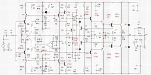
Found service manual for real Revox 285.
Different transistors. Rails 52V
I guess original printout did not show transistor types or values, and someone added it manually.
Luckily, Q109 is not BC327 🙂
add a repeater
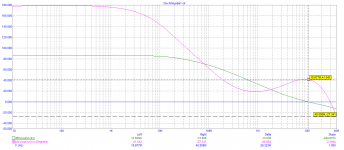
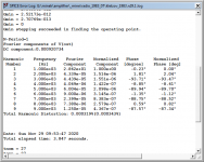
This is my latest results.
I also tried Jfet input - it looks like it's a drop-in replacement.
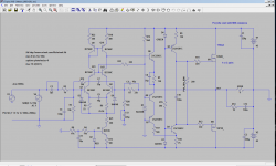
Sim attached (for both: BJT and JefFet input)
LSK170A/B work just fine, same results overall as with BJTs.
I checked my stash of Jfets - I have LSK170 grade D.
Unfortunately grade C and D does not work in this simulation.
I thought that since we have LTP coscoded here, this is great opportunity to use Jfets..
I also tried Revox voltage shifter with a resistor - bad idea.
I also tried Jfet input - it looks like it's a drop-in replacement.
Sim attached (for both: BJT and JefFet input)
LSK170A/B work just fine, same results overall as with BJTs.
I checked my stash of Jfets - I have LSK170 grade D.
Unfortunately grade C and D does not work in this simulation.
I thought that since we have LTP coscoded here, this is great opportunity to use Jfets..
I also tried Revox voltage shifter with a resistor - bad idea.
Attachments
-
 kletzov_1983.n29.1.png75.2 KB · Views: 194
 -
 kletzov_1983.n29.1.opg.png78.6 KB · Views: 206
 -
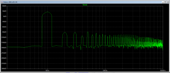 kletzov_1983.n29.1.fft.png25.2 KB · Views: 201
 -
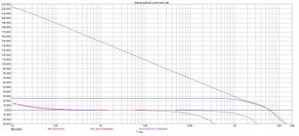
 kletzov_1983.n29.1.thd.png24.1 KB · Views: 188
 -
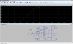 kletzov_1983.n29.1.square.png57.3 KB · Views: 136
 -
kletzov_1983.n29.1.asc11.3 KB · Views: 83
-
kletzov_1983.jfet.asc10.4 KB · Views: 76
Last edited:
OK. Thanks Maxim!
Otherwise, everything else look OK?
Any idea why LSK170 Jfets grade C/D don't work, but grade A are OK?
Otherwise, everything else look OK?
Any idea why LSK170 Jfets grade C/D don't work, but grade A are OK?
Last edited:
>All right. That's the question. Common mode voltage. Ignore or fight ?
I'm going to assume this is rhetorical question 🙂
If you don't know the answer, how would I know?
I'm going to assume this is rhetorical question 🙂
If you don't know the answer, how would I know?
>All right. That's the question. Common mode voltage. Ignore or fight ?
I'm going to assume this is rhetorical question 🙂
If you don't know the answer, how would I know?
2 ways.
1) enter feedback for tracking.
2 . to fix the problem.Switch scheme the amplifier to the inverting option.
1 option will complicate the scheme of the amplifier.
3 just ignore the problem.
Last edited:
I went back to posts Hayk (kokoriantz) hinted about few days ago.
Eg. post #75
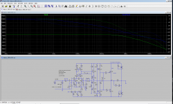
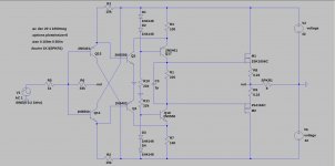
Here is the sim of it. It's simple, symmetrical (that's disputable if this is good or bad 🙂), perhaps something can be made of it?
What you think of it?
2 * CCS can be added on top and bottom of LTP, and maybe 2 buffers
between LTP and VAS?
As is, distortions are little bit too high, I guess, but it's simple.
Eg. post #75
Here is the sim of it. It's simple, symmetrical (that's disputable if this is good or bad 🙂), perhaps something can be made of it?
What you think of it?
2 * CCS can be added on top and bottom of LTP, and maybe 2 buffers
between LTP and VAS?
As is, distortions are little bit too high, I guess, but it's simple.
Attachments

I have a similar circuit, an inverted amp, ~ 0,006 THD, but a little to high DC:
This is CFA ?
I guess not...
Last edited:
>A simple amplifier with a high slew rate voltage
This one is CFA amp!
That's why it needs servo... notorious DC offset issues.
This one is CFA amp!
That's why it needs servo... notorious DC offset issues.
- Home
- Amplifiers
- Solid State
- Unusual amp from 1987