>Beautiful amplifier turns out. With mirror
Told you! 🙂
I didn't sim your mirror, but I have a feeling my mirror (in my sim post #665) was running at smaller current..
I also changed CCS at the bottom.
I might be mistaken, but I thought optimal current for LTP transistors is 1mA .. 1.2mA (each).
Told you! 🙂
I didn't sim your mirror, but I have a feeling my mirror (in my sim post #665) was running at smaller current..
I also changed CCS at the bottom.
I might be mistaken, but I thought optimal current for LTP transistors is 1mA .. 1.2mA (each).
Last edited:
Excellent. The amplifier looks good even on the circuit. the fast and the furious r34c10 started to work.Кг 0,0005 %
Last edited:
Excellent. The amplifier looks good even on the circuit. the fast and the furious r34c10 started to work.Кг 0,0005 %
R34/C10 is supposed to make it faster?
And faster and more stable.
I try to make do with fewer resistor ratings.I counted the mirrors to 300. the output constant is less than.At low current, the distortion increases . When high current diffused ,the noise growing . Compromise!I might be mistaken, but I thought optimal current for LTP transistors is 1mA .. 1.2mA (each).
Last edited:
>I didn't sim your mirror, but I have a feeling my mirror (in my sim post #665) was running at smaller current..
>I also changed CCS at the bottom.
>I might be mistaken, but I thought optimal current for LTP transistors is 1mA .. 1.2mA (each).
>I also changed CCS at the bottom.
>I might be mistaken, but I thought optimal current for LTP transistors is 1mA .. 1.2mA (each).
answered from above. We haven't optimized the diagram yet, but only the sketch
Attachments

Last edited:
Also, one more inconvenient thing - zener voltage depends on rail voltage (yours 12V, mine 24V).
Perhaps there is a way to make it work with any rail voltage. Use resistor instead of the zener?
Perhaps there is a way to make it work with any rail voltage. Use resistor instead of the zener?
But this is not essential.It's just support.Try changing the voltage of the Zener diode.There only the power dissipation will change on the transistors.You can choose a mode in which the first two transistors in the cascode can be low-power,and the lower, third, more powerful.
Last edited:
It's essential to me. With zener 12v i can't use this amp with 45V rails. I have several different PSUs with different voltages, and i want my amps to work without any changes, on different voltages. Within reason of course.
I think this zener can be replaced with one more CCS plus resistor...
I think this zener can be replaced with one more CCS plus resistor...
Actually, 24V Zener works fine for rails 32V and up, so that should be fine for me.
Update: 12V Zener also works fine for 45V rails. Don't know why, but in the first sims,
12V Zener didn't work well for 45V rails, output wave was asymmetrical..
Update: 12V Zener also works fine for 45V rails. Don't know why, but in the first sims,
12V Zener didn't work well for 45V rails, output wave was asymmetrical..
Last edited:
Maxim,
1) Can you show Thd and FFT for your sim?
2) What is power dissipation on Q2 ?
With 45V rails:
It looks like over 200mW.
That's kind of unusual for LTP CCS...
I think Q2 has be TO-126 transistor, or CCS need to be changed to allow 2N5551
Q1/Q3 also run over 100mW. Too much...
1) Can you show Thd and FFT for your sim?
2) What is power dissipation on Q2 ?
With 45V rails:
It looks like over 200mW.
That's kind of unusual for LTP CCS...
I think Q2 has be TO-126 transistor, or CCS need to be changed to allow 2N5551
Q1/Q3 also run over 100mW. Too much...
Last edited:
>Classic. 2-component feedback.
With this kind of feedback (33k + 33k + (5p .. 33p)), can't get square waves to look good.
With 'normal' feedback (33k/22pF) square waves look perfect.
With 2-component feedback, C must be at least 33p, but SR is getting lower...
============
Tried few sims, it looks like with 2-component feedback SR is lower.
Maybe I'm wrong, still testing..
Last edited:
1 Distortion at rated power and low powerMaxim,
1) Can you show Thd and FFT for your sim?
2) What is power dissipation on Q2 ?
With 45V rails:
It looks like over 200mA.
That's kind of unusual for LTP CCS...
I think Q2 has be TO-126 transistor, or CCS need to be changed to allow 2N5551
Q1/Q3 also run over 100mW. Too much...
2IMD
3 I'll show you the DC analysis .in two variants.With equal power across the cascode transistors and an alternative
Attachments
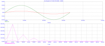

In the presence of high-quality capacitors, a 2-component OOS is not necessary.But I'm used to it
The IMD graph is not accurate, and the analysis time was set to be short.It should be even lower.
R13 increase the nominal value to 750-1kom and the cascode will not warm up
The IMD graph is not accurate, and the analysis time was set to be short.It should be even lower.
R13 increase the nominal value to 750-1kom and the cascode will not warm up
Last edited:
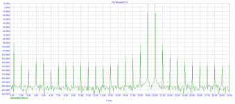
My Thd profile looks worse, but I'm testing with lower current LTP input
and 1-component feedback. Everything else should be the same...
and 1-component feedback. Everything else should be the same...
My Thd profile looks worse, but I'm testing with lower current LTP input
and 1-component feedback. Everything else should be the same...
I don't have THD, but IHD. They are smaller
It's time to draw the PCB
Last edited:
So soon??? 🙂
We need higher slew rate. The 1st sim I published yesterday, had SR=50V/us.
Now my latest sim is back to 15V/us
We can't have all small transistor in input LTP running hot at 100mW-250mW, on the other hand - with lower
dissipation, RS goes down...
We need higher slew rate. The 1st sim I published yesterday, had SR=50V/us.
Now my latest sim is back to 15V/us
We can't have all small transistor in input LTP running hot at 100mW-250mW, on the other hand - with lower
dissipation, RS goes down...
Attachments
Last edited:
- Home
- Amplifiers
- Solid State
- Unusual amp from 1987