Since it's built with 2 pairs of output transistors, I expect real 120W
per channel (my speakers are rated 6 Ohm).
Perhaps you could try to squeeze more, but why?
Post #326 contains the schematic 'as built' - 1 output pair shown, in real build 2 pairs were used with
source resistors 0.33 Ohm (0.22 Ohm would be better).
Earlier schematics were slightly different.
per channel (my speakers are rated 6 Ohm).
Perhaps you could try to squeeze more, but why?
Post #326 contains the schematic 'as built' - 1 output pair shown, in real build 2 pairs were used with
source resistors 0.33 Ohm (0.22 Ohm would be better).
Earlier schematics were slightly different.
Last edited:
I asked coz I wanted to see what transformer power to buy for this build. Can you please do measurements with different quiescent currents to see the effect of this on distortion?
One more thing - if you you are going to use more than 1 pair of output devices, ideally they should be matched (for Vgs), at higher current.
2 upper devices should be matched to each other, and 2 lower ones to each other.
Differences between upper and lower devices doesn't matter.
2 upper devices should be matched to each other, and 2 lower ones to each other.
Differences between upper and lower devices doesn't matter.
The distortion will increase and the quiet current will be unstable.What happens if not matched?
You need to take transistors from the same batch. If the spread is large, then you will need to increase the resistors in the sources
Last edited:
Thank you.
If I couldn't get matched transistors, what should be the value for source resistors
If I couldn't get matched transistors, what should be the value for source resistors
>in real build 2 pairs were used with source resistors 0.33 Ohm
If using more than 1 pair, source resistors always should be used, doesn't matter transistors are matched or not.
Matching will never be perfect...
I wanted to use 0.22 Ohm, but I only had 0.33 in stock.
More pairs - higher values for source resistors.
If pairs are extremly badly matched, and working hot (at high power), they can fail.. (burn like this: )
)
Using multiple pairs lowers distortions, and lowers output impedance of the amp.
If driving 4 Ohm speakers at high power levels, 2 pairs are recommended.
If using more than 1 pair, source resistors always should be used, doesn't matter transistors are matched or not.
Matching will never be perfect...
I wanted to use 0.22 Ohm, but I only had 0.33 in stock.
More pairs - higher values for source resistors.
If pairs are extremly badly matched, and working hot (at high power), they can fail.. (burn like this:
)Using multiple pairs lowers distortions, and lowers output impedance of the amp.
If driving 4 Ohm speakers at high power levels, 2 pairs are recommended.
Moving on - Kletzov amp (1983)
I've been trying to make these maps little bit faster; 15V/us is OK, but would be nicer to have a faster amp.
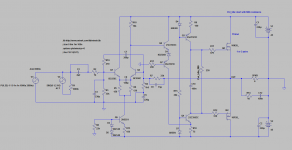
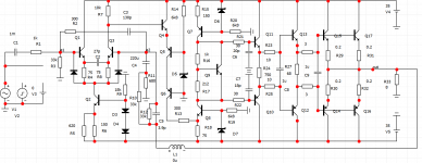
Here is an attempt: the same configuration for the output as before - Wiederhold style - but with LTP input instead of op-amp.
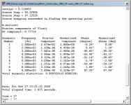
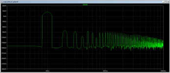
Thd and FFT look very good - but not as good (yet) as latest Maxim's amp..
Square waves look nearly perfect, it's much easier to tune, and more stable.
Slew Rate is about 50V/us - not too bad for such a simple amp, so this would be an improvement over op-amp based amps.
This is based on amp designed by V. Kletzov, published in Russian Radio magazine in July 1983, so it predates LMK amp.
Стр. 51 журнала <<Радио>> № 7 за 1983 год
This amp here gives better numbers than Vhex I tried to simulate couple hundred posts ago, and this is just 1st attempt.
LatFets are used here just for simplicity of the simulation.
Maxim, perhaps you see some way to make this better?
Perhaps lower LTP current to 1mA per transistor? Shift voltage in some other, better way (not using Zener)?
I've been trying to make these maps little bit faster; 15V/us is OK, but would be nicer to have a faster amp.
Here is an attempt: the same configuration for the output as before - Wiederhold style - but with LTP input instead of op-amp.
Thd and FFT look very good - but not as good (yet) as latest Maxim's amp..
Square waves look nearly perfect, it's much easier to tune, and more stable.
Slew Rate is about 50V/us - not too bad for such a simple amp, so this would be an improvement over op-amp based amps.
This is based on amp designed by V. Kletzov, published in Russian Radio magazine in July 1983, so it predates LMK amp.
Стр. 51 журнала <<Радио>> № 7 за 1983 год
This amp here gives better numbers than Vhex I tried to simulate couple hundred posts ago, and this is just 1st attempt.
LatFets are used here just for simplicity of the simulation.
Maxim, perhaps you see some way to make this better?
Perhaps lower LTP current to 1mA per transistor? Shift voltage in some other, better way (not using Zener)?
Attachments
Last edited:
I have a model of this amp, and in real life I know how it works .I'll try to make it better. I'll show you tonight
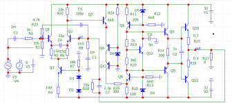
Promised modernised Клецов .Close to the original .It seems to be a beautiful scheme turned out
R4 the selection of zero
R4 the selection of zero
Attachments
Last edited:
The Rush has sufficient gain to work without IPS. See post 61.Promised modernised Клецов .Close to the original .It seems to be a beautiful scheme turned out
R4 the selection of zero
The Rush has sufficient gain to work without IPS. See post 61.
What's not to like about this scheme ? Sounds good ,but it might be better
1polus 35 kHz . with a loop gain of 65 dB at this frequency
Last edited:
>I have a model of this amp, and in real life I know how it work.
You mean you have a real amp (hardware)? Or just a simulation?
You mean you have a real amp (hardware)? Or just a simulation?
Will try to play with it later today. But I think it looks promising.Somewhere like this
If there was a way to make this amp faster with op-amp, I would prefer op-amp, but discrete LTP will do 🙂
>I have a model of this amp, and in real life I know how it work.
You mean you have a real amp (hardware)? Or just a simulation?
Was once.Long ago. I'm not interested in him now
AD829 will help you. You've seen the diagram, but it's complicatedWill try to play with it later today. But I think it looks promising.
If there was a way to make this amp faster with op-amp, I would prefer op-amp, but discrete LTP will do 🙂
- Home
- Amplifiers
- Solid State
- Unusual amp from 1987