Did you try what Moschfet said in post #597?
Without input R, and without any signal, there are oscillations.
This 1Meg R was solving this...
Correction: just adding the cap (220p/330p) solved this. No R needed.
Without input R, and without any signal, there are oscillations.
This 1Meg R was solving this...
Correction: just adding the cap (220p/330p) solved this. No R needed.
Attachments
Last edited:
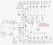
There used to be a 1Meg resistor placed at the very input, but this was messing up your square wave simulations.
In real build should we include it?
In real build should we include it?
I have a closed entrance . Through the capacitor and the nominal value of the resistor is an order of magnitude less. In the microcapsule, it is not needed ,this resistor
In post #604 : resistor R42 is not needed?
R42 is an equivalent of the 1meg I had before (e.g. R21 in post #586).
R42 is an equivalent of the 1meg I had before (e.g. R21 in post #586).
A ground resistor is not required at the virtual zero point.There's zero. in post 604, the role of resistor 42 is fake,you can put it on,you can't put it on.Purely for the simulator, some programs don't like its absence on certain dimensions.
Last edited:
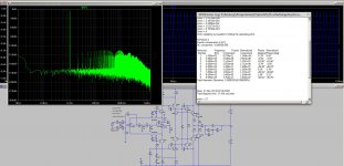
That's not what I mean. The simulation of THD runs faster and a little more precisely if the pulse generator in the circuit does not run passively.These schematics are missing input RC network.
With R from input to the ground it sims just fine without any signal sources.
>all my amps that I design whit LTspice whit such low THD begin to oscillate in reality
Well, I hope this one won't 🙂
3 amps has been already built from this thread, and while their THDs were not quiet as low as this one, but they were close, and all 3 worked just fine.
Maybe you can share some of your designs?
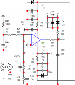
This is the amp, that I am working on yet. It is class B/C, because the power transistors are switching onley on at specific current ( ~30mA).
From the princip is my circuit very close to yours.
Regards Patrick
Attachments
Yeah, similar - but you are driving VAS from power pins of op-amps.
There is no global feedback?
There is no global feedback?
What happens when the trasistors with a common base in the power supply of the op-amp break down ?
😕 burn out?
Al currents in the op amps are not on their limits.
Then the power contacts of the operational amplifier have the full supply voltage. The cost of a good operational amplifier is much higher than the price of a 1n4148 diode. You only need a few piecesThen the speaker have bad DC.
This method of pumping is quite popular. I dabbled myself.Here is the actual diagram, based on the diagram from the Radio magazine.This method of pumping is quite popular. I dabbled myself.Here is the actual diagram, based on the diagram from the Radio magazine.Protective diodes D1/D4 are supplied.Parallel to the Zener film capacitors.
Attachments
Last edited:
No, I assumed that one of the transistors burned out.
Unfortunately, I don't know exactly what you're going to do with the diodes. Maybe it's also because of my poor English ...
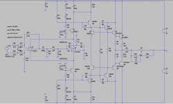
Who wants can play with this circuit or can show me something new 🙂 :
edit :Ahh OK, I see want you mean, thank you
Unfortunately, I don't know exactly what you're going to do with the diodes. Maybe it's also because of my poor English ...
Who wants can play with this circuit or can show me something new 🙂 :
edit :Ahh OK, I see want you mean, thank you
Attachments
These amplifiers have problems with through current. As a result, the amplifier may burn out.That's why you should take precautions.
- Home
- Amplifiers
- Solid State
- Unusual amp from 1987