>Is the quiescent current normal ?
Yes. No anomalies. 147mA per device.
Everything looks good.
Squares are square, sinuses are sinusoidal, capacitance load is ok. 🙂
Clip looks ugly in the lower half, even with LR...
This will require some solution, I think.
The models for sure aren't perfect, but I guess no worse than for other devices.
These models for LetFets are from Ian Hegglun, and I'm sure he knows his models...
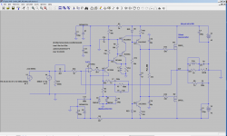
Changed latfet models to the actual 'dual die' Exicons 20N20/20P20.
Adjusted idle current to 280mA per fet.
In order to get square waves right, had to adjust C7=150pF.
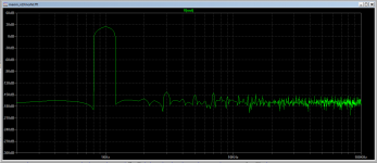
Clip (1.7 Vpp) on the lower half looks much better, almost acceptable 🙂
Sinus 1.2 Vpp look the same as before.
Rise time approx 3us
Adjusted idle current to 280mA per fet.
In order to get square waves right, had to adjust C7=150pF.
Clip (1.7 Vpp) on the lower half looks much better, almost acceptable 🙂
Sinus 1.2 Vpp look the same as before.
Rise time approx 3us
Attachments
I wonder, for double die latfets - should I leave the same value of gate stoppers, or lower it?
Changed latfet models to the actual 'dual die' Exicons 20N20/20P20.
Adjusted idle current to 280mA per fet.
In order to get square waves right, had to adjust C7=150pF.
Clip (1.7 Vpp) on the lower half looks much better, almost acceptable 🙂
Sinus 1.2 Vpp look the same as before.
Rise time approx 3us
Minek, this is extremely high fidelity, and should sound as the original source. Not sure if you can try with BJTs and HexFETs for the output to see if similar results can be achieved? also the idle current is kinda high
Idle current is high, because these are 'double' fets - 2 fets in one case.
Since optimal idle for 1 fet is 140mA, now it's gonna be double: 280mA.
But there is no law that says you must run it at such high idle current.
Many amps with latfets run at 40-60mA per device and they are fine,
just slightly less optimal from the theoretical "perfect Thd" level 🙂
I'll try it at different levels, and we will see..
I'm sure no one can tell the difference by listening to music...
Run 280mA if you have big heatsinks and live in cold climate country, and it's winter coming 🙂
Last edited:
Minek, this is extremely high fidelity, and should sound as the original source. Not sure if you can try with BJTs and HexFETs for the output to see if similar results can be achieved? also the idle current is kinda high
I'm pretty sure you can replicate this with BJT (that's what Maxim will build) - actually BJTs should have slightly lower Thd than Latfets...
And as we've seen from simming hexfet Wiederhold versions, similar numbers can be obtained with vertical fets too.
I'm using Latfets in all the sims, because that simplifies everything,
and using the same outputs allows me to compare different input and VAS arrangements.
Once everything works ok, we can try to replace latfets with different outputs...
Maxim has version with BJTs (with output triples and other bells and whistles).
Last edited:
560ma . Not much?
280mA per 1 'double' fet. 140mA per 1 die.
Well, always can go lower if needed...
With 80mA per dual fet, Thd is just a tiny bit up, everything else should work the same.
No need to adjust any values.
No need to adjust any values.
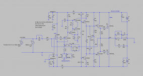
Here is vertical fet example.
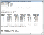
Almost the same numbers as for LatFet version. Perhaps it can get better, but it looks like it's a compromise between performance for square waves and for sinus waves..
C6=10p is better for square waves, but C6=12p is better for sinus/Thd.
Correct value will have to be selected with oscilloscope tests.
Anyway, these are minuscule differences, that most likely won't matter in reality...
Attachments
Thank you Minek, Maxim. This is an excellent next-build candidate!
I shall try 39p in series with 12p if it fulfills the compromise
I shall try 39p in series with 12p if it fulfills the compromise
Here is vertical fet example...
Nice amp, all my amps that I design whit LTspice whit such low THD begin to oscillate in reality.
Try to run the simulation without the puls source, delete it and run it again 😉
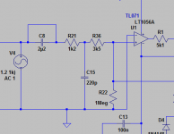
These schematics are missing input RC network.
With R from input to the ground it sims just fine without any signal sources.
>all my amps that I design whit LTspice whit such low THD begin to oscillate in reality
Well, I hope this one won't 🙂
3 amps has been already built from this thread, and while their THDs were not quiet as low as this one, but they were close, and all 3 worked just fine.
Maybe you can share some of your designs?
- Home
- Amplifiers
- Solid State
- Unusual amp from 1987