That's it. C6 10pF and everything works.
Meander learned to look in LTspice
Meander learned to look in LTspice
Attachments
Last edited:
Maxim, you don't sleep?
Beautiful square waves 🙂
You also tweaked couple of other values (R,C)..
Beautiful square waves 🙂
You also tweaked couple of other values (R,C)..
Even better.
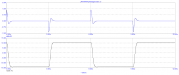
It is necessary to look at the meander signal and the base of the first transistor .The distortion graph at 20 kHz would be interesting to see.
It is necessary to look at the meander signal and the base of the first transistor .The distortion graph at 20 kHz would be interesting to see.
Attachments
Last edited:
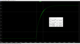
From the square waves, it looks like Slew Rate is approx. 30V/us
Much better than before.
Still 0.0 % Thd
FFT for 1kHz sinus looks flatter (2nd, 3rd, 4th harmonics),
and everything is lifted up by 10 dB.
Looks like Q6 (in my sim) has to be low beta (A type). C type is more prone to trigger oscillations.
Are BC546/556 OK in there?
Q4 is running at over 80mW, little bit high for a small transistor?
Last edited:
Put a 150ohm resistor between emitters Q1 and Q4 .Your fileFrom the square waves, it looks like Slew Rate is approx. 30V/us
Much better than before.
Q4, is running at over 80mW, little bit high for a small transistor?
Bad idea. a 100-200 Ohm resistor between the Q1 and Q2 ' on your file you need to putThanks Maxim!
Last edited:
quite so. Otherwise the gain dropsWorks like a champ. 40mW power.
Q1 and Q2 ?
Not Q1 and Q4 ?
1) Resistor in the collector of Q1 (between Q1 and Q2) lowers power consumption in Q1 only. Q4 stays at 80mW.
2) Resistor between emitters of Q1 and Q4, lowers power consumption in Q4, which is what we need, right?
2) Resistor between emitters of Q1 and Q4, lowers power consumption in Q4, which is what we need, right?
>Hi, I downloaded and run the sim, post #543. Is it OK ?
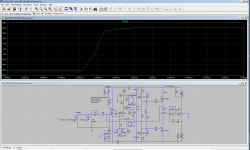
This is latest of mine, C7 increased to correct shape of square.
We are still not clear where the resistor should go Q1/Q2/Q4 🙂
so I left it out. The worst case - Q4 needs to be bigger.
Maxim is using Multisim, and from what I've seen, square waves looked better in his Multisim simulations...
I'm getting different shapes/small oscillations depending on the amplitude of the square signal.
It may look good for 2 Vpp, but worse for 1.6 Vpp
It's still "work in progress", but getting there...
Attachments
Last edited:
And the signal level of the square wave at the output of the generator can be reduced? I'm sure the level is high
Minek, how does it sound, have you run the wave simulation and listened to it yet. One can easily spot sound signatures listening to it even with zero distortions.
You should also use the spread in component tolerances, as is you are using identical components with zero tolerance. It is all there in the manual. One can actually make a real amplifier and listen to it before touching a soldering iron or ordering a component.
- Home
- Amplifiers
- Solid State
- Unusual amp from 1987