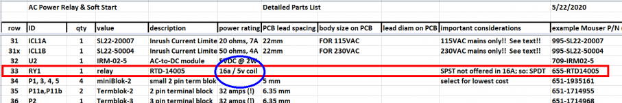
That relay doesn’t appear to be the proper type... it’s 20V with 8A contacts. The BOM asks for 5V coils and 16A contacts.
RTD14005 TE Connectivity / Schrack | Mouser
RTD14005 TE Connectivity / Schrack | Mouser
Check the circuit design and schematic and Parts List of H9KPXG once again.
I think you'll find that it contains an AC-to-DC converter whose output is +5V DC. This is applied to the coil of the relay. I think you'll find that the parts list calls for "RTD-14005" which is a relay with a 5VDC coil and 16 ampere contacts. Makes sense: with a 5V supply we need a relay whose coil operates at 5V.
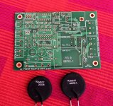
Unfortunately your photographs in post #100 above, appear to show a different relay with a different part number. Your relay appears to have a 20 volt coil and only 8 ampere contacts. That's wrong, twice. I couldn't find a datasheet or a pinout; if the pinout of that substitute relay is different than the RTD-14005, then it is wrong three times -- an award winner. Suggest you unsolder that relay and install the one called for in the Parts List.
_
I think you'll find that it contains an AC-to-DC converter whose output is +5V DC. This is applied to the coil of the relay. I think you'll find that the parts list calls for "RTD-14005" which is a relay with a 5VDC coil and 16 ampere contacts. Makes sense: with a 5V supply we need a relay whose coil operates at 5V.
Unfortunately your photographs in post #100 above, appear to show a different relay with a different part number. Your relay appears to have a 20 volt coil and only 8 ampere contacts. That's wrong, twice. I couldn't find a datasheet or a pinout; if the pinout of that substitute relay is different than the RTD-14005, then it is wrong three times -- an award winner. Suggest you unsolder that relay and install the one called for in the Parts List.
_
Attachments
Yes. I ordered by using a link to a Mouser BOM posted earlier in this thread so I wanted also make sure nothing was off so no one else has this issue. Nope, traced it all the way through from the BOM to web order and invoice. Right part number ordered but wrong part showed up.They sent the wrong part? That’s a bummer. I’m sure they will sort it out.
...Unfortunately your photographs in post #100 above, appear to show a different relay with a different part number. Your relay appears to have a 20 volt coil and only 8 ampere contacts. That's wrong, twice. I couldn't find a datasheet or a pinout; if the pinout of that substitute relay is different than the RTD-14005, then it is wrong three times -- an award winner...
_
I have an extra RTD-14005 relay, PM me your address and I'll ship it to you right away.
This is the award I needed, thanks Mark!
")
Eureka! You can install a 250 Joule(!) ICL into this ACPR+SS board
I just received a couple of 250 Joule rated Inrush Current Limiters from Mouser.com, and I'm delighted to say they can be used with the existing (Rev.C) AC Power Relay & Soft Start PCB. You might remember from post #1 above, that the standard ICLs called for in the Detailed Parts List, are rated for 125 Joules. So these new ones are twice as rugged, twice as beefy, and twice as macho. For those who may be interested, example calculations of Joule requirements are also included in post #1.
These great big ICLs are made by Ametherm. If you think you really want or really need a 250 Joule ICL, the one I recommend for 115VAC mains is Mouser part number 995-MS32-20008 [32 mm diameter / 20 ohms cold / 8A max steady state current], and the one I recommend for 230VAC mains is Mouser part number 995-MS32-50006-L [32 mm diameter / 50 ohms cold / 6 amps max steady state current]. Their .pdf datasheets are attached below.
The footprint on the ACPR+SS PCB Rev.C is deep enough and wide enough to accommodate these 32mm ICLs without touching neighboring components. The drill holes are juuuuust big enough that the "115VAC mains" ICL slides in easily. However the "230VAC mains" ICL has slightly larger diameter leads, so you'll need to reduce them a teeny bit. Sandpaper, needle file, scraping with diagonal cutters, anything you try will probably work. Don't worry, an ICL is not Static Sensitive and it survives an Electro Static Discharge with zero damage. So sand / file / scrape to your heart's content.
Maybe, some day, I might revise the PCB layout and include slightly bigger drill holes, to make the PCB comfortably accept the "230VAC mains" version of the 250 Joule ICL. If there is another compelling reason to make a PCB revision, I'll roll in this change too. Meanwhile, get out your sandpaper and spend a relaxing ten minutes of your time, in exchange for bragging rights about Two Hundred Fifty Joules!! And shake your fist at the lucky DIYers in USA, Japan, Canada, and other places. These fortunate souls can use the 115VAC part number of 250 Joules ICL, which needs no sanding or shaving or scraping.
_
Attachments
Last edited:
I have an extra RTD-14005 relay, PM me your address and I'll ship it to you right away.
RTD-14005 received and installed on PCB. The board now passes the 100w bulb test and the meter says I am getting full voltage at the output. Again thank you!
Hello All -
I have 10 PCBs left for members who are interested. Send me a PM if you would like to get them.
Regards,
Subbu
Hi Subbu - sent your a PM a while ago - any boards left?
Thanks
I recommend you buy the MOSFETs listed on the schematic and the Parts List. Checking at Mouser Poland this morning, both of those components are in stock and ready for dispatch. Here they are:
https://pl.mouser.com/ProductDetail/Microchip-Technology/TN2106N3-G?qs=WSAGJ7rh4G3XS1HPd1TpBQ==
https://pl.mouser.com/ProductDetail/Microchip-Technology/TP2104N3-G?qs=xVZHMx80kUqxi7pwl07eiQ==
The Parts List gives part numbers for Mouser Electronics, because Mouser has an excellent international presence and a good reputation among diyAudio members.
If you want to create a list of potential substitutes for these two MOSFETs, take note of column J ("important considerations") in the parts list; then compare the datasheet of the original MOSFET with the datasheets of your proposed substitutes.
Had an idea for this project, while I have been trying to select switches.
If one built the 12v version (vs the more common 5v version), one could tap off the Meanwell to power the 12v capacitance based switches.
Perhaps future versions of the board could include a plug for 12v output to the switch.
If one built the 12v version (vs the more common 5v version), one could tap off the Meanwell to power the 12v capacitance based switches.
Perhaps future versions of the board could include a plug for 12v output to the switch.
That's a fun idea, to swap the 5V AC-to-DC converter out and swap in a 12V model! You'd need a new relay with a 12V coil, and you'd probably need new current limiting resistors for the LEDs and the optoisolator. I'll let you check the datasheets of the MOSFETs and the ICs to decide if they are okay, or can be easily modified / swapped.
Standby power (equipment "off") will be higher, about 2.5X higher, but maybe you don't care.
Standby power (equipment "off") will be higher, about 2.5X higher, but maybe you don't care.
Last edited:
May I kindly request to include PCB pads for a single bicolor LED in a possible next revision ? With a common cathode LED pads for a 3 pin connector would be enough. It is unusual to have to drill 2 holes for 2 LEDs of which one lights in the Off state (which could be called Standby).
Last edited:
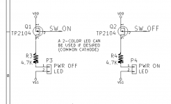
You can use a bicolor LED with the current (Rev.C) version of the PCB. Simply connect Anode-Red to P3 pin 1, connect Anode-Green to P4 pin 1, and connect Cathode-Common to P3 pin 2. Schematic fragment, snipped from post #1, below.
Then you have a 3-wire cable which runs from the LED to the PCB. Two of the three wires attach to connector P3, and one of the wires attaches to connector P4.
Here are some possibilities: Mouser USA link
_
Then you have a 3-wire cable which runs from the LED to the PCB. Two of the three wires attach to connector P3, and one of the wires attaches to connector P4.
Here are some possibilities: Mouser USA link
_
Attachments
Yes but I meant 3 PCB pads in 2.54 mm pitch so that the LED can be soldered straight to the PCB (wires bent in angle). Also 2 extra pads in 2.54 mm pitch for a 2 pin Molex KK for the power on/off switch would be nice as it switches no significant current.
That way the board can be used with LED connector and switch connector just behind the front cover with the power transformer behind it close to the IEC inlet, far away from the audio stuff.
Just suggestions, Mark.
That way the board can be used with LED connector and switch connector just behind the front cover with the power transformer behind it close to the IEC inlet, far away from the audio stuff.
Just suggestions, Mark.
Last edited:
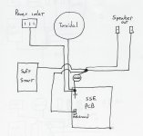
Mark, I tried to follow your advice on integrating a CL-60 into the grounding circuit of my Tubelab SSE. Please see attached drawing. The speaker out, pcb, soft start are grounded to a point that is connected to chassis ground through a CL-60. The power inlet and toroidal ground are connected directly to chassis ground. Did I get this right?
... it's a low resistance CL-60, sometimes it's a combination of them.
Gently, I suggest you study the photograph attached to post #16 of this thread. It's a stereo amplifier which uses this mains relay & soft start PCB (yellow arrowhead). But what ELSE do you see? Look hard.
Hint: look at the intersection of row_4 and column_4 of baseplate holes.
Another hint: some mounting bolts are silver colored because they are metal & conductive. Other mounting bolts are white colored because they are nylon & insulating. The photo includes some of each.
_
Attachments
- Home
- Amplifiers
- Power Supplies
- PCB: low voltage On-Off switch drives AC mains relay \ includes soft start .. H9KPXG