....
I guess it would be ok to piggyback a 47k (or others for even smaller values) just to see how it goes?
yup, 47K, 43K,39K - whatever you have in drawer, trimpot in series will cover that
P1 Trimpot to max = clockwise 25 turns = output ≈ 5k ohm?
.....
be inventive - find a way to check with ohmmeter
I can't remember and I don't care much about CW/CCW even on my own pcbs, always trusting only what DMM is showing
........
Not sure about how to connect the trimpot (not p1) in series? In-out is easy but where do I connect pin 3 / gnd?
sorry, I wasn't precise - I meant P1, not additional trimpot
just correct 10K position, as already told
Last edited:
Thank you ZM, good advices as always. Measure output I would have anyway [emoji1]
It would/will be SO cool if baby-F4 comes to life after just this issue!
[emoji1317] david
I‘m a bit in type-before-thinking-mode, most of the advices become clear just after i go „huh?“... [emoji51]
It would/will be SO cool if baby-F4 comes to life after just this issue!
[emoji1317] david
I‘m a bit in type-before-thinking-mode, most of the advices become clear just after i go „huh?“... [emoji51]
Please confirm the part you used for Q11 and your value for R8.
R8 is the bummer: 22.1r instead of 22.1K

now comes what I hate: ordering 2 pieces worth $1, $20 shipping. So have to invent a new project to get to the required amount for saving shipping. (Which brings an advantage back, haha)
other values, like 27.4K in the unlikely event that
22k isn't enough.
In the basket, as well as some for r9...

many thanks, Dennis & ZM!
Jaa, jaa, ha-ha-ha!damn Greenhorns

now it's closing in...
Heya!
Got a spare hour to try doing the correction.
Replaced R8 (22.1K) on first channel, switched on (first with light-bulb, then fully) and here's BIAS! instant 0.13mA, offset between 0.00 and 0.03 mA.
Next question: Why does it not get warm? The channel has been on for ~15 minutes, no real temp-rise.... (heatsink and device are both room-temp, 18°C)
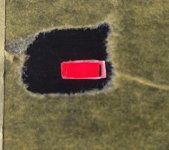
When I was in need of a little distraction, I went to the chassis and tried my mechanic skills, making a prototype of the LED-indicator:
Since I have dozens of rectangular leds, I'm using them for the front. Cutting out a hole 5 x 2 mm is a bit of a challenge though. (As one can barely see, the LED sits snugly, but the cutout got half a mm too long). I luckily made it on a spare part.
Next try: round the led, make the hole 5 x 2 mm with round ends...
edit: That yellowish stuff is the masking tape protecting the anodized aluminium.
Attachments
Did you set P1 to max value before you power up the other channel. With R9=5K
(and I'm assuming R8=22.1k) the TL431 will give fairly high Vgs voltages even with P1
set to max (~5k) and you may already get a healthy amount of current
flowing through the mosfets. And if P1 was close to zero that current will be very
high.
(and I'm assuming R8=22.1k) the TL431 will give fairly high Vgs voltages even with P1
set to max (~5k) and you may already get a healthy amount of current
flowing through the mosfets. And if P1 was close to zero that current will be very
high.
- Home
- Amplifiers
- Pass Labs
- My F4 build (questions, bragging, and other thoughts)

