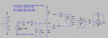
I was also thinking about this. "The normal mode of operation" as I would call this H2 generator, is the assumption that you have an "ordinary" amplifier, ie not SE, an amp that does not enhance second harmonic and that does not invert phase (most commercial amps). In that case, by adding H2 circuit, you would introduce a small amount of positively-phased second harmonic, but since it is inverting, you would have to invert speaker connections at the output of am amp, in order to "bring back the overall phase". But, by doing this, you would invert the phase of the second harmonic, which would now become nagative, as is the intention of the circuit.
The problem arises if your amplifier already inverts the phase (Zen amp for example). By adding H2 circuit, you make one more inversion at the input, so now you have to reverse your speaker connection, in order to get "the right phase". But, in this case, you will get positive second harmonic, both from H2 and the Zen amp, and your result may not be as expected.
Hence, for such cases, it is necessary to "invert the phase once again". That also applies if you don't want to invert speaker connections in case of an "ordinary amp".
So, the simplest thingvwould be to build an opamp based phase reverser, which is basically an opamp which input goes to - input, with 100% feedback. It't easy to do, I've seen such circuit on some "subwoofer phase switches". On the other side, I don't know what (negative) efect can an additional opamp with 100% feedback have on the sound, so maybe we want a different solution.
Sorry if all of this sounds confusing, but it is actually very simple. Remember, the aim is to get the right overall phase at the speaker, while adding a small amount of negatively-phased second harmonic.
I am saying this because I have seen the tube buffers added on front of amps that do not invert phase. The result of this is the addition of positively-phased second order harmonic, but we want it negative.
Now if what I said is confusing enough, maybe Nelson can draw a simple schematic
P.s. Just had an idea :lightbulb: What about using a 1:1 transformer at the input as phase reverser?
Yes, way out of my depth.
I will just wait for the DIYAudio version which hopefully has the switching option.
The idea is to avoid a lot of relays etc.
This sims ok.
You can leave out the buffer, if you are ok with the volume being lower in the mid position and in either end position. The following inverting amp can also be omitted if you just vant the unity gain
R10 and R11 is the potentiometer here set in mid position (22k lin pot)
This sims ok.
You can leave out the buffer, if you are ok with the volume being lower in the mid position and in either end position. The following inverting amp can also be omitted if you just vant the unity gain
R10 and R11 is the potentiometer here set in mid position (22k lin pot)
Attachments
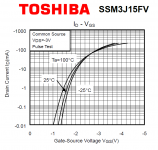
is there a combination of jfet type (j111, j310 etc), bias and supply voltage that could give the same harmonic signature but with more output level? 4V instead if 1.5V
Finding out the answer will require a LOT of lab experiments using a distortion tester and a bunch of other equipment. However I think that if you decide to try it, you will have a lot of fun and expand your knowledge considerably.
I have a feeling, an opinion (but no hard data!), that to make a large amplitude H2-enhancer you might get better results from a MOS field effect transistor than from a junction field effect transistor. Looking through a pile of datasheets, I found the very lovely curve attached below. It's a MOS field effect transistor. The output versus input appears to be quite a nice square-law characteristic, which in the realm of opinions instead of data, ought to give quite a nice amount of 2nd harmonic distortion. I've attached the manufacturer's datasheet.
Give it a try, see what you think. Replicate Nelson Pass's H2 experiments but this time using a PMOSFET instead of an NJFET. Fame, glory, and tremendous fun awaits you.
_
Attachments
Have several questions re the "original" H2 Generator board...
I understand that each board was calibrated to produce "optimum" level of H2s and the relevant volts was noted on each. I have marked the pot to allow resetting if it inadvertently moved or moved for experimentation.
Across what points on the board would a measurment be made to assure resetting to the original condition?
Other than music coming from the speakers with the H2 inserted between preamp and amp, is there a simple way to know that it is working?
Is there somewhere for an LED to be added which verify circuit operation?
I am aware that a bulb could be added across the DC input points but that only assures that SMPS is supplying power.
Would it be possible to add a mini-led voltage display across the points where the calibration voltage is determined to indicate both operation and verify oltage setting?
IF so, what display specs would be required?
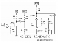
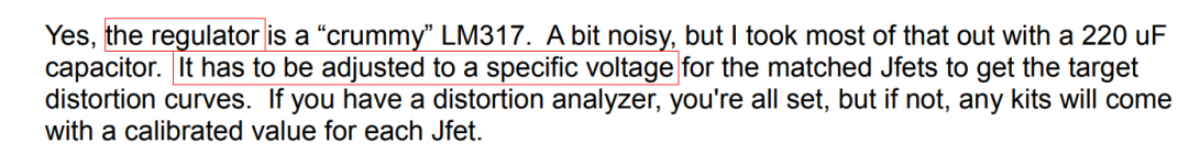
Maybe the pronoun "it" might be the source of your confusion (2nd red box in attached H2 manual below)? To what does "it" refer?
"It" is the voltage regulator (1st red box in attached H2 manual).
The regulator has to be adjusted to a specific voltage, to get the target distortion curves. Nelson Pass measured the H2 distortion on your individual board, while he adjusted the regulator's output voltage. He wrote a voltage on your individual board, where he thinks the H2 distortion is Just Right. You are free to fiddle around with the potentiometer and to adjust the regulator's output voltage however you like. But if you ever want to set it back to NP's "Just Right" voltage, the number is written right there on the board.
Simply attach your digital voltmeter between node "V+" (the voltage regulator output) and "GND". Twirl the pot control until the DVM shows the same number as NP wrote on your board. Done.
If you want to build or buy a digital voltmeter display which is permanently connected between "V+" and "GND", and which is glued to the H2 PCB, that is your right. You own it, you can DIY it however you wish. Perhaps one of these cheap jobbies from eBay might do what you want? I haven't bought or used any of them myself so I can't promise they are easy to interface or they give accurate readings.
5PCS Mini Blue DC 0-30V LED Panel Voltmeter 3-Digital Display Voltage Meter 708624425963 | eBay
12V-60V Car Marine Motorcycle LED Digital Voltmeter Voltage Meter Battery Gauge | eBay
Waterproof Monitor 12V Battery Meter 2.5-30V DC Auto Gauge Digital Voltmeter LED | eBay
3pcs DC 0-30V Red LED 3-Digital Display Voltage Meter Voltmeter Panel Motorcycle 6971216072843 | eBay
_
Attachments
Thanks, Mark. See my follow-up questions in maroon below...
Maybe the pronoun "it" might be the source of your confusion (2nd red box in attached H2 manual below)? To what does "it" refer?
"It" is the voltage regulator (1st red box in attached H2 manual).
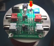
I see the "it" as well as the P1 adjustment pot on which I made hash marks to denote Nelson's setpoint.
However, I do not see the 317 regulator position marked either on the actual board or the Red/Green PC board rendering in the manual.
Which component on the board is the regulator? The tall black cylinder next to P1?
The regulator has to be adjusted to a specific voltage, to get the target distortion curves. Nelson Pass measured the H2 distortion on your individual board, while he adjusted the regulator's output voltage. He wrote a voltage on your individual board, where he thinks the H2 distortion is Just Right. You are free to fiddle around with the potentiometer and to adjust the regulator's output voltage however you like. But if you ever want to set it back to NP's "Just Right" voltage, the number is written right there on the board.
Simply attach your digital voltmeter between node "V+" (the voltage regulator output) and "GND". Twirl the pot control until the DVM shows the same number as NP wrote on your board. Done.
Will Nelson's adjustment voltage be measurable even without RCA inputs and outputs connected?
If you want to build or buy a digital voltmeter display which is permanently connected between "V+" and "GND", and which is glued to the H2 PCB, that is your right. You own it, you can DIY it however you wish. Perhaps one of these cheap jobbies from eBay might do what you want? I haven't bought or used any of them myself so I can't promise they are easy to interface or they give accurate readings.
Appreciate the recs!
5PCS Mini Blue DC 0-30V LED Panel Voltmeter 3-Digital Display Voltage Meter 708624425963 | eBay
12V-60V Car Marine Motorcycle LED Digital Voltmeter Voltage Meter Battery Gauge | eBay
Waterproof Monitor 12V Battery Meter 2.5-30V DC Auto Gauge Digital Voltmeter LED | eBay
3pcs DC 0-30V Red LED 3-Digital Display Voltage Meter Voltmeter Panel Motorcycle 6971216072843 | eBay
_
Here is a link to a data sheet.:
http://www.ti.com/lit/ds/symlink/lm317.pdf
If you fire up Google, the pictures are the 3 terminal IC with a metal heat spreader.
http://www.ti.com/lit/ds/symlink/lm317.pdf
If you fire up Google, the pictures are the 3 terminal IC with a metal heat spreader.
Here is a link to a data sheet.:
http://www.ti.com/lit/ds/symlink/lm317.pdf
If you fire up Google, the pictures are the 3 terminal IC with a metal heat spreader.
Bear with me here...
When I google LM317, I get something like the figure below which shows the regulator as having 3 legs and a tab with hole at the top.
I DO not see any components like this on the H2 board. I DO see 3 half cylinders with 3 legs but NO tab at the top. The one closest to the P1 pot has its curved surface facing the pot. I am guessing the round vs flat surfaces determine the pin assignment?!
The tutoring is appreciated!

Have several questions re the "original" H2 Generator board...
I understand that each board was calibrated to produce "optimum" level of H2s and the relevant volts was noted on each. I have marked the pot to allow resetting if it inadvertently moved or moved for experimentation.
Across what points on the board would a measurment be made to assure resetting to the original condition?
Other than music coming from the speakers with the H2 inserted between preamp and amp, is there a simple way to know that it is working?
Is there somewhere for an LED to be added which verify circuit operation?
I am aware that a bulb could be added across the DC input points but that only assures that SMPS is supplying power.
Would it be possible to add a mini-led voltage display across the points where the calibration voltage is determined to indicate both operation and verify oltage setting?
IF so, what display specs would be required?
If the objective of the circuit is subjectively perceptible and detectable, there would be no need to mark any special point in the trimpot. It is assumed that the effect would be subjectively perceptible, unless it is only a placebo. The previous reference mark is according to a subjective appreciation and possibly corresponding to a sample that is considered as representative. Nothing is extensive to universal, no matter how big the representative sample is under which the possible improvement that this circuit supposes is postulated. As the level of distortion fluctuates with the level of the signal at each moment, it may happen that according to the variable level of the musical passage and its variation thresholds, the perception changes in some particular cases and with different listeners and listening environments .
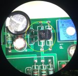
I am so brave, that I dare to bend the pins on one of the components! And then snap a photograph. Look on my works, ye mighty, and despair. (P. B. Shelley)
_
Thanks for bending over backwards
to help me out!NOW since there is no tab at the top as with the LM317 shown in my pic, how are the pins ID'd from left to right...or from top to bottom in your right-hand photo?
The package is called TO92.
Here is a link to the data sheet.
See page 3.
http://www.ti.com/lit/ds/symlink/lm317l-n.pdf
Here is a link to the data sheet.
See page 3.
http://www.ti.com/lit/ds/symlink/lm317l-n.pdf
Maybe you would want to consider a circuit where the inverter is
optionally on the input side or output side. Picking one versus the other
allows listening to + phase second harmonic or - phase.
I thought the little bias adjustment on the unit would allow you to zero H2, or go to either in-phase or anti-phase harmonics.
Why switch where your inverting buffer is, if you can change between in-phase or anti-phase with the adjustment?
Or is the concept that you'd never adjust the harmonic/bias (to preserver the preset amount) but you may wish to flip between in-phase and anti-phase?
I see that such a simple circuit still causes a lot of confusion.
I will try to explain the way I understood it,someone else may correct me if I am wrong:
1. This circuit, as is, is a common-source little preamp with the attenuation on the imput, with the aim of not providing net gain (ecen though there is signal gain-it is inherent in the design)
2. As such, it always flips the phase of the signal, and it generates second harmonic which is always in positve phase.
3. But, since the circuit inverts the overall phase, in order to get it back you have to do one more inversion. Assuming tha your power amp is non-inverting, the simplest thing is to reverse the speaker cables. By doing this, you have your overall phase "back to normal", but the second harmonic that was generated by a H2, which is positive, is now flipped, and looks as negative.
Easy, isnt't it?
By the simple change of voltage you can change the amout of second harmonic distortion. Do do confuse this with phase change. Phase can be changed at the speaker terminal, ir by addition of another line level circuit that flips the phase and ideally does not introduce distortion (it could be a j-fet, mosfet, IC and maybe a transformer). I hope Nelson can provide us with a nice solution (transformer+buffer).
Regarding the voltage meter, once we know the useful range of voltages, we could build an analogue meter. I would call it "sweetness" meter
Finding out the answer will require a LOT of lab experiments using a distortion tester and a bunch of other equipment. However I think that if you decide to try it, you will have a lot of fun and expand your knowledge considerably.
_
Thanks for your advice! I will try but first need to build the distortion tester...
it seems this can be done with a scope and a notch filter to remove the 1Khz fundamental tone
is there any schema that I could use?
Count backwards through the posts on this thread, starting from yours.
Your post will be "Zero". Then a post from member Vix will be "One". Then a post from member AdamThorne will be "Two". When you get to "Twelve", stop. Is that what you mean by a schema?
You could also read the very first post in this thread, written by Nelson Pass on 22 September 2018. He is the person who designed this H2 circuit.