
Look at these
https://www.neutrik.com/en/products/audio/powercon (Search “powercon”)
https://www.amphenol-aerospace.com/products/power-products (search ”circular aviation”)
I try to avoid using connectors we commonly use for audio signal for power connections. Nothing preventing you from using appropriately specced XLR connectors though.
put a caps on the amp boxThanks for the info pinkfloyd4ever. I decided on external power so I can be less careful with shielding. I was getting a very slight hum; which I only hear with my ear pressed to the speaker now.
I have a lightly used 4U aluminum faceplate with two holes for LEDs and 1 19MM hole for an MFR# MC010920 push button on/off. Ideal when used with Mark's soft start CB.
I offer this for shipping costs, which have been $22.00 for the other ones I have moved on.
Send me a VM if interested.
I offer this for shipping costs, which have been $22.00 for the other ones I have moved on.
Send me a VM if interested.
Attachments

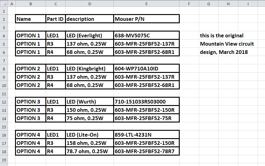
Hi Mark,The LED used in the M2x "Mountain View" input stage daughter card, has been annoying M2x builders for quite a while. It just got even worse, after Mouser decided to stop selling individual units of that LED; now their minimum order quantity is 4000 pieces! Digi-Key still sells it in quantity=1, but diyAudio members seem to strongly prefer buying from Mouser.
So I bought a bunch of different LEDs from Mouser, made by several top-tier manufacturers, and tested them in Mountain View. The good news is that three of them are quite acceptable and give excellent performance in Mountain View. The not so good news is, the new LED requires slightly different resistor values. It all works in the existing PCB; you just have to buy a matching trio of parts: (an LED ; an R3 resistor ; an R4 resistor). Same board, same schematic, new component values. Have a look at the schematic attached below.
The trio of coordinated parts is (LED1 + R3 + R4). Consult the table of options, attached below, and choose a trio. Then purchase those parts values and install them in your Mountain View boards. Easy! The table of options is presented twice; first as a screen capture image (for easy viewing on the Forum), and also as an Excel spreadsheet inside a .zip archive (for easy copy and paste of cumbersome part-numbers). The component values shown are the results of my lab measurements on Mountain View cards and the three new LEDs.
With three different LED possibilities, there's a MUCH greater chance that your Mouser in your country, will have at least one of them in stock and on the shelf, ready for dispatch. I just checked each of them at Mouser locations which previously were "difficult" (Mouser Finland, Ecuador, Portugal), and these LEDs are in stock & available in quantity=1, today. Nice!
I should mention that the LED and resistors R3 and R4 are not in the signal path of Mountain View; they are simply bias components whose only job is to set the operating currents of signal-handling devices J1 and Q2. Changing the LED has no effect upon the sonic signature of Mountain View. Which I am sure is an assertion that several people will decide to verify or refute, for themselves 🙂
I will work with Forum Moderators to get this information integrated into the official Bill Of Materials for Mountain View.
Mark Johnson
_
I´m building the Mountain Wiev card now, and experiencing with the same issue regarding the LED MV5075C.
Many thanks for your table of options; I just wanted to clarify the following: in the table the 2nd option has the same R values as the original one - is that right? Because you wrote that the new LEDs require new R values for R3 and R4, but obviously not for the 2nd option?
Many thanks is advance.
Anybody enjoying the IPS6 cards as much as I do?
My M2X works very well with my MLTL Single Driver (Fostex 167E) speakers with the IPS6 inside. I followed MJ's instruction to set the boards properly and then bliss all the way!
Thank you Mark, as usual, for your generosity!

My M2X works very well with my MLTL Single Driver (Fostex 167E) speakers with the IPS6 inside. I followed MJ's instruction to set the boards properly and then bliss all the way!
Thank you Mark, as usual, for your generosity!
Attachments
Could use some guidance on my M2x. I recently finished a dual mono version but having issues on the right channel. It hums and has no music playing, and the d44h11 and AD797 on the Cedarburg boards get VERY hot to the touch.
Here is the information and troubleshooting I have done so far:
- I swapped input boards to test on the other channel and confirmed both Cedarburg boards work fine.
- I confirmed +/- 25 Volts at the board
- I checked the 4 posts of the input boards and get, +25V, -25V, -1.05V (but keeps climbing up), and -1.5V
- I reflowed the solder on the boards
- I confirmed my washers were not touching any of the parts on the input board
- I confirmed the 4n35 is on correctly
- I checked and confirmed all parts look correct
- I am able to easily set DC offset on the board down to 0
Any help is appreciated!!!
Last edited:
What is your source driving the M2x? Have you swapped R and L cables from the source ruling it out as the issue?
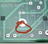
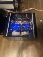
Might have found my issue. The lock washers I bought were a bit too large and I noticed the bottom right daughter board post had the lock washer sitting a bit low and it was tightened onto the trace below it that comes from R5.
This wasn’t a problem on the other board because there weren’t any close traces.
I’m going to buy some smaller lock washers tomorrow and swap them out. Hopefully that solves my issue.
I should have known better and search more for the smaller ones….
Here’s a picture of the area I am referring to.
This wasn’t a problem on the other board because there weren’t any close traces.
I’m going to buy some smaller lock washers tomorrow and swap them out. Hopefully that solves my issue.
I should have known better and search more for the smaller ones….
Here’s a picture of the area I am referring to.
Attachments
Anybody enjoying the IPS6 cards as much as I do?
Congratulations on a beautiful build! Those black PCBs look sexy as hell with ENIG gold traces.
I happen to think IPS6 is doubly delightful. First you get the tweak-lover's delight of matching the JFETs and dialing the 20-turn trimmer pot for perfect balance. Next you get the music-lover's delight of listening to the rare and delicate beauty of a (very) high gain transconductance amplifier, driving an Edcor interstage transformer.
*transconductance amplifier means it's a voltage controlled current source, whose open loop output impedance is extremely high (> 100 Kohms). All the other IPS cards are voltage controlled voltage sources, and they drive the Edcor transformer very differently.
Has anyone tried DC-specific IEC connectors for the umbilical connection between amp and external power?:
https://www.newark.com/schurter/3-104-044/power-entry-conn-rcpt-8-8a-294vdc/dp/99AC3565
https://www.newark.com/schurter/3-101-786/power-entry-conn-plug-8-8a-294vdc/dp/99AC3564
They're super inexpensive, and likely to support anything I build in the future. I think I'm going to give them a try.
I'd enlarge the holes I'm currently using for pass-through:
I´m building the Mountain Wiev card now, and experiencing with the same issue regarding the LED MV5075C.
Many thanks for your table of options
The table attached to post #3318 of this thread, copied below for convenience, is correct. The resistor values in that table are correct and the LED part numbers are correct. All four of those tabulated options will work equally well in Mountain View. If you are suspicious about one particular option, or concerned that it may not work, you can disregard that option and choose one of the other three. Whichever you prefer.
Many thanks Mark, option 2 is the easiest way, because no need for new resisitors. There was nothing suspicios, I'm sorry if I gave that impression.The table attached to post #3318 of this thread, copied below for convenience, is correct. The resistor values in that table are correct and the LED part numbers are correct. All four of those tabulated options will work equally well in Mountain View. If you are suspicious about one particular option, or concerned that it may not work, you can disregard that option and choose one of the other three. Whichever you prefer.
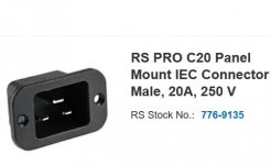
For my dual power supply, I used IEC connectors with the pins the opposite way to "normal" leads.Has anyone tried DC-specific IEC connectors for the umbilical connection between amp and external power?:
https://www.newark.com/schurter/3-104-044/power-entry-conn-rcpt-8-8a-294vdc/dp/99AC3565
https://www.newark.com/schurter/3-101-786/power-entry-conn-plug-8-8a-294vdc/dp/99AC3564
They're super inexpensive, and likely to support anything I build in the future. I think I'm going to give them a try.
I'd enlarge the holes I'm currently using for pass-through:
The theory being that a 240v lead will not plug in.
Something like this.
Attachments
If that is at the power supply output, the exposed pins are not safe. If the power supply is on with no cable connected, a person can get zapped.
Another suggestion is to label non-standard power outlets and amplifier power inputs with the type of power out/in so there is no confusion when the power supply is separate from the amplifier.
Be safe.
Another suggestion is to label non-standard power outlets and amplifier power inputs with the type of power out/in so there is no confusion when the power supply is separate from the amplifier.
Be safe.
Or use Speakon or XLR 5-pin for the DC power. Extremely safe and reliable. XLR's current rating is way beyond the demands of M2.
For clarity.If that is at the power supply output, the exposed pins are not safe. If the power supply is on with no cable connected, a person can get zapped.
Another suggestion is to label non-standard power outlets and amplifier power inputs with the type of power out/in so there is no confusion when the power supply is separate from the amplifier.
Be safe.
Those are input sockets on the amp, so not live unless the plug (Which has shielded sockets) is in place.
Plugs are on leads hard wired to the P/S. 🙂
I am looking for 2 "additional" Norwood boards to use on the front end of my VFET build. I love my M2x with Norwood so I thought that might be my first non Pass design. Any suggestions on how to get a couple. I have some IPS 6 and 7 and Cedarburg boards to give away if anybody wants them. No charge. Just PM me. US only please.I'm friends with two DIYA members that have better ears than mine, and who both have built all eight M2x input cards. So each of them has a complete collection; they're not missing any information.
As it turns out, they happen to agree: both say that Norwood is their #1 favorite of them all. They also say it was a lot of fun to build and listen to the full set.
Me? I love all my children.
Thanks,
Don
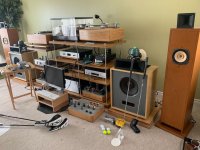
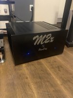
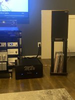
Another M2x is born! Dual mono rocking the Cedarburg boards!
I corrected my right channel hum issue… just had oversized lock washers on the right channel daughter board posts digging into a trace on the board it shouldn’t have been.
I corrected my right channel hum issue… just had oversized lock washers on the right channel daughter board posts digging into a trace on the board it shouldn’t have been.
Attachments
- Home
- Amplifiers
- Pass Labs
- The diyAudio First Watt M2x