Pferrell went through the list, as discussed at various points in this thread. I installed copper tape, and mu metal shielding on the input transformer, and used shielded power transformer, and had them as far apart as possible in Mono Blocks. I still had hum.
Be sure to check the source components, and interconnects. I have found external sources of hum as often as internal. I had a noisy pre-amp before, a fritzy interconnnect, and more lately found that long RCA IC cables causing hum. Fixed with XLR cables, and transformer to feed the M2x with RCA. Even my EL34 PP tube amp is silent with the XLR-transformer-RCA chain.
The ground can also be contaminated, although I do t know enough to really discuss that possibility.
One issue being that I/we tend to use sensitive speakers, which tend to showcase hum.

My solution to the problem of hum in my M2x was to build an external power supply which eliminated the hum completely. I have no idea if the fact that it was external was the key factor or that it was a completely new power supply and there was something wrong with the original one.
If you have a supplier you trust in China (from the post earlier), why not ask if they can get you a part with the proper specs?
A quick internet search will give you some insights re: key characteristics of COG caps vs. other types. tl;dr - they are very stable to drift due to temperature change and also capacitance drift due to dielectric wear over the life of the cap.
So, why were they picked? I don't know, but Mark does. I can try to guess and work through the question.
The caps specified by Mark were/are +- 5% tolerance out of the box. You may note that the capacitors you posted the specs for are also +- 5% tolerance out of the box. Good match.
I don't see a spec for expected temperature effects / stability over time. COG / NPO generally implies that the capacitance will be stable over the life of the cap and with temperature changes. Polypropylene film caps do not generally share those traits. So, that might be an issue. If the absolute capacitance can vary by as much as 10%, but stability is critical... hmmmm. When Mark chooses a part ... in my experience, it's generally for a good reason. I'd consider the dielectric chosen in this case to be important.
Voltage Rating - The parts Mark chose are 100VDC rated. I'd stick with that or higher unless you know why you could go safely lower.
Cost / Availability / Form Factor and Size / Other considerations - You may note that in the BoM, Mark notes 5mm lead spacing, but that of the parts examples he listed, one has 2.5mm lead spacing. So, as Mark noted, bending the leads a bit within reason won't matter. You don't want SMD parts. Radial termination would be nice, and should not be tough to get. You'll likely see variants with all kinds of bends in the legs. It wouldn't make any difference to me.
So, I'd ask your trusted local person if they can get you any NPO/COG caps of 5% or tighter tolerance. Radial termination, with lead spacing from 2.5mm to 5mm. My guess is that if they're reputable, they'll have a number of options for you.
Others may have differing / better advice, and may offer some corrections and additions, but that's how I'd personally work through the situation at my (uneducated) level of understanding.
Enjoy your M2x! It's a wonderful amplifier, and Mark's additional boards are a treat to play with (Even if I still have two yet to build that are far... far... overdue).
Sorry for the delay in answering, I moved houses and forgot to take the time to thank you! Anyways, thanks for digging into why and how this device was chosen, I'll figure out a way to get the recommended part as it doesn't seem the one I posted earlier will do the trick as nicely.
Cheers,
Arthur
How does ACA-220 v2 differ from v1.6?I tend to agree with the organic and non-fatiguing qualities of the Mtn View. I spent many long listening sessions with that one, as it had excellent preservation of tone as well as pace and timing. The instruments I'm more familiar with are acoustic and electric guitar and bass, plus piano, drums, flute and vocals. If an amplifier doesn't get those right, it won't last in my system.
Prior to building my first ACA, my system had been all-Naim electronics, with a modified NAP-250 as my power amp. The Naim gear tends to do really well with tone even with the basic models. Improvements with timing, clarity and imaging come with the more elaborate (& expensive) power supply options. The NP Class A amps have have given me new appreciation for organic and realistic sound quality. The M2x has proven to be a step above my last ACA build (the ACA-220 v2), mainly in dynamic headroom. It has also opened up some details in a few recordings that I am very familiar with.
Some of the IPS designs that I have in my queue include a couple variations on the Mtn View. I have my own take on the Moffett Field, as well as one that I am calling Fremont after the headquarters location of Linear Systems. This topology allows for some fun experimentation with devices and bias currents.
The big difference with the ACA-220 is a linear PSU delivering over 28V to the amp. That and the higher bias current allow the IRFP140 output devices to run better in their sweet spot. The result is improved bass and dynamic detail across the audio range.
The closest comparison would be a pair of standard ACA monoblocks in parallel bridged configuration. The ACA-220 moves the performance up from there.
The closest comparison would be a pair of standard ACA monoblocks in parallel bridged configuration. The ACA-220 moves the performance up from there.
Hi,
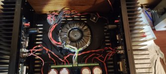
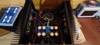
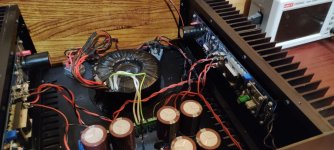
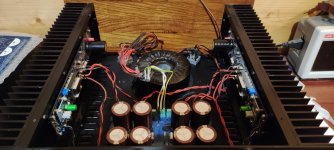
I'm almost done with my M2 build with one slight problem. When connecting a phone or Chromecast Audio to inputs I get a lot of hum, whereas when nothing is connected to inputs, M2 remain silent, no hum at all. Is this related to cross channel ground loop ? How to solve it ? I've already tried different wiring paths with no effect.
I'm almost done with my M2 build with one slight problem. When connecting a phone or Chromecast Audio to inputs I get a lot of hum, whereas when nothing is connected to inputs, M2 remain silent, no hum at all. Is this related to cross channel ground loop ? How to solve it ? I've already tried different wiring paths with no effect.
Attachments
-
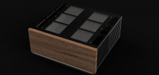 M2X_2022-Jun-29_05-41-32AM-000_CustomizedView11595292051.png270.5 KB · Views: 205
 -
 IMG_20220628_223526.jpg250.1 KB · Views: 209
 -
 IMG_20220628_223501.jpg242 KB · Views: 214
 -
 IMG_20220628_223443.jpg266.8 KB · Views: 190
 -
 IMG_20220628_223438.jpg318.6 KB · Views: 200
 -
 IMG_20220628_223434.jpg279.5 KB · Views: 209
So, I managed to find solution to my cross connection ground loop. I've disconnected input GND signals from ampboards. Then, connected both input grounds together and connected them to star GND on my PSU board. I do not know if it is a correct aproach but that resolved my hum problems.
Attachments
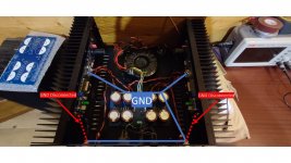
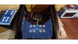
I'm trying to sort this out in my head.connected both input grounds together and connected them to star GND on my PSU board
As it stands now, the source device output grounds are now connected to your PSU ground.
Having them together probably isn't doing anything different 'looking back' at the source, as they likely are connected together there anyway.
However, now I don't see how your L,R channel boards will have a proper reference for the incoming signal. Perhaps it doesn't really matter, as the signal is all AC and any DC difference should be filtered out.
Kind regards,
Drew
Please excuse my opamp ignorance, I am building the last of the double secret daughter cards ( rhymes with peterburg) and I don't see a opamp socket in the BOM. I want to be able to take out the AD797 and use it in the future for a Ship of T Bon Homme Richard card. Can I just use a dip-8 socket as in the IPS7 BOM (milled pins, gold, 110-87-304-41-001101)
There is a Detailed Parts List but no BOM. See post #4343 in this thread. The Detailed Parts List doesn't list a socket for the opamp.
Post #4343 says:
so it is assumed that Cedarburg builders who want to socket their IC, will either already possess a parts drawer full of DIP sockets, or know how to buy some. For example, by purchasing the same ones used in IPS7.
Post #4343 says:
WARNING: Cedarburg is not a suitable project for beginners or builders who want instructional videos, step by step photographic Build Guides, or training wheels style tutorials. If you think you need more ...
so it is assumed that Cedarburg builders who want to socket their IC, will either already possess a parts drawer full of DIP sockets, or know how to buy some. For example, by purchasing the same ones used in IPS7.
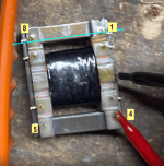
quick question about the Edcor transformers. I just received a pair in the mail and put some copper EMI tape around the transformer. After taping them both I checked continuity of each pin on the transformer and realized pin #8 (does appear to be used) shows resistance between the body of the transformer. I checked all wires of the transfomer and confirmed none of them are touching the emi copper tape.
I removed the tape to confirm it was not causing the problem and still showed pin #8 has some connection to the body of it. Should this be a concern or just move on? I checked and the other transformer does not have the same continuity.
Looking at the m2x schematic and the schematic of the transformer, Pin 8 does nothing. Can I proceed on?
Attachments
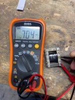
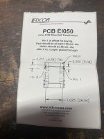
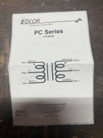
Edcor pin 1 is offset for keying. In your photograph, copied below, that's at the upper right. Your ohmmeter probes are connected to the Edcor metal frame {black probe}, and Edcor pin 4 (not pin 8) {red probe}.
At the moment I happen to have two Edcor PC600-15K transformers in my lab, so I repeated your experiment. I used my ohmmeter to measure (A) the resistance from Edcor metal frame to Edcor pin 4 ; (B) the resistance from metal frame to pin 8; (C) the resistance of a 1/4 watt, 1% tolerance, 1 Megohm resistor. I did these 3 measurements on both transformers. In all cases the 1 Meg resistor measured 1.007 megohms, and the Edcor metal frame to pins 4 and 8 measured Off Scale (>20 megohms).
Thus: my results didn't match yours. I found open-circuit from the not-connected pins, to the Edcor metal frame.
Perhaps you'll be comforted by this little tidbit: pins 4 and 8 are not connected to ANYTHING on the M2X PCBs. You can verify or refute this claim yourself, experimentally. Just buzz out each of the M2x amp channel PCBs with your continuity tester. You'll discover that neither Edcor pin 4 nor Edcor pin 8, are connected to any other signal nets or power nets on the M2x PCBs. They are floating, Not Connected. They affect nothing, and nothing affects them.
_
Attachments
yes. thank you, Mark, for the correction. Pin 4 is the one I was testing. One transformer shows open between pin #4 and the metal body. The other shows a rising continuity. I will just mark the transformer and see how it performs in the circuit. I do see neither pin 4 nor 8 are used in the m2x schematic which should allow me to move forward with the build! Thanks!!
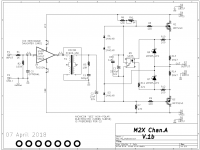
Hi, I am not sure if this is the correct place to start a question but I'm currently working on the M2 amp. My input stage and main amps behave in an unexpected way. I give it 25V and set the power supply's limiting current to 0.1A. At first, the current is stable but after 30 seconds the current begins to spike and in order to compensate for the spiking current the voltage drops, can someone explain why? Should I be concerned?
when current is stable:

When current spikes:

when current is stable:
When current spikes:
Have a quick look at post #3355 of the Official M2 thread. Each of the amplifier channel boards ramps up its current sloooooooowly, as (R6 and R7) charges capacitor C3. The asymptotic final value after hundreds of seconds, is Vfwd_Q5_LED / (R13 series R14) which is around 1.3 amperes per channel for the push pull MOSFETs. Then add the worst case (biggest possible) Input Stage supply current. One point three something amperes per channel.
_
_
Attachments
Last edited:
The problem is that the PS was set to limit current to 0.1A, not a lot when the amp draws nearly 1.5A per channel.
I saw some people using irfp9140 with the irfp240 mosfets for this amp.
Mouser is out of the 9240 and I have some 9140 on hand. Do I need to make any changes to the schematic if I use 9140?
thanks.
Mouser is out of the 9240 and I have some 9140 on hand. Do I need to make any changes to the schematic if I use 9140?
thanks.
- Home
- Amplifiers
- Pass Labs
- The diyAudio First Watt M2x