My cinemags arrived today. One of the 5 has a label backwards from the rest. I used the notch by the pins to locate pin 1.
I finished wiring and proceeded to testing. PSU +/-15v was quick and easy. Setting 0mV was also easy. I did an initial set and then noticed a little drift. I let it warm up a little and did a final adjustment once it settled down.
Installing jumpers is a very tight squeeze with the cinemags. I bent the pins a little and they worked.
Here’s where I need input from mighty ZenMod. At 6db setting I’m seeing minimal gain on scope. On 12dB setting I’m seeing ~6dB gain. Did I install cinemags in reverse? I snipped the unconnected pins and dropped pin 2 into the C2 hole on the board. Any ideas?
Time for sleep. I’ll continue tomorrow. I hope to figure out gain, then bench sound test, and finally main system test tomorrow.
Attachments
be careful , to not melt them
though, as far my 2 cells are working these days, rotating CMOQ is resulting in same functionality, so there must be something else fishy**
confirm that you have same level of signal pre and post buffer
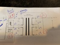
**see enclosed
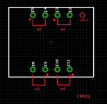
w means winding, red dot means phase
//////////////////////////////////////////////////////////////
anyway, while I'm preparing this post, I see you wrote in a meantime
confirm that signal pre-post buffer
though, as far my 2 cells are working these days, rotating CMOQ is resulting in same functionality, so there must be something else fishy**
confirm that you have same level of signal pre and post buffer
**see enclosed
w means winding, red dot means phase
//////////////////////////////////////////////////////////////
anyway, while I'm preparing this post, I see you wrote in a meantime
confirm that signal pre-post buffer
Attachments
Hello all,
I've been reading this whole thread lately as am looking for a good balanced pre, and getting more interested in this... I am almost there to final decision..
As a basic (lowish) level builder, may I ask ZM/all, if it makes sense:
- could the balanced Iron Pre be used as a unity gain device without output transformers? (may be I am cursing and Iron pre would loose its identity.. but lowering gain might be required in my system/and maybe others)
- could 20K Muses remote controller be used as "volume pot"? Has anyone implemented this into any build by the way?
- are inputs dc coupled (I am guessing not) and how much is tolerated? If not, generally speaking, shall "cure" be implemented at source output or Iron Pre input in case of necessity?
Thanks a lot, and keep up the good work!
Hello all,
I've been reading this whole thread lately as am looking for a good balanced pre, and getting more interested in this... I am almost there to final decision..
As a basic (lowish) level builder, may I ask ZM/all, if it makes sense:
- could the balanced Iron Pre be used as a unity gain device without output transformers? (may be I am cursing and Iron pre would loose its identity.. but lowering gain might be required in my system/and maybe others)
- could 20K Muses remote controller be used as "volume pot"? Has anyone implemented this into any build by the way?
- are inputs dc coupled (I am guessing not) and how much is tolerated? If not, generally speaking, shall "cure" be implemented at source output or Iron Pre input in case of necessity?
Thanks a lot, and keep up the good work!
you did something funny with your post, all I can is Reply - there is no Quote...... though with Multiquote I can do this
anyway - yes, you can omit xformes , thus having buffers only ; yes , you can use whatever sort of attenuator you wish and like
everything is DC coupled ; if you need AC coupling (caps) - generally when source is separate black box, better to do it in source position
why routing some DC potential through interconnect cables - if nothing else , that's just bad practice, leading to trouble in first possible occasion
hvala herr. Zen Mod, not sure what I did but very likely it's my fault ") sometimes when I use computers they crash on me whilst working for others.. go to know..
sometimes when I use computers they crash on me whilst working for others.. go to know..
Thanks for you reply, it seems the balanced Iron Pre could fit in my project/system, also using BAL (for main amp in my case) and SE (for SubW) outputs at the same time seems feasible.. little more meditation and will be time to dive!
sometimes when I use computers they crash on me whilst working for others.. go to know..Thanks for you reply, it seems the balanced Iron Pre could fit in my project/system, also using BAL (for main amp in my case) and SE (for SubW) outputs at the same time seems feasible.. little more meditation and will be time to dive!
to paste here what I wrote to you in PM , for benefit of other Greedy Boyz; even if I wrote all of that already, no harm in repeating it:
Hi Mateo
No, I don't have spare Toshibas - if you are going for Iron Pre, then buy Linear system JFets from Store
Regarding Iskra , they are extremely good, but I don't have any for trade
I did explain entire logic behind Iron Pre and Iron Pumpkins approach - idea is to use active devices for buffers only, where they're least harmful to sound (practically invisible when done properly) and using Xformer for gain, which is soundwise superb approach , when using proper xformers
besides, when using xformer for gain in balanced mode, you're getting SUSY "effect", which is inherent thing for balanced xformers
Signal Energy Preservation is main goal here ...... and that's finally achieved in Iron Pumpkins, where output autoformer is serving not just as ( settable) gain device but also as superior level setting device - no more attenuator as we are used to have
though, this is more talk for thread, so other Greedy Boyz can benefit, too
NB - this is my approach and my choice - to have as much is possible neutral preamp - some other people prefer other solutions
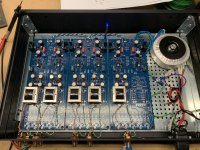
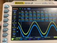
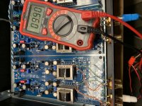
ZM - Pix attached. I tried to measure and take many notes to see if something is obvious.
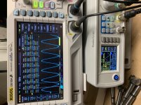
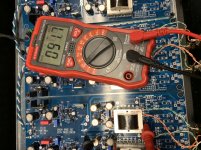
Before and after buffer voltage is same - so unity gain. See scope pic. Values dance a little on the scope, .918V, .923V, .945V, etc.
I'm getting good +/- 15V from PSU.
All boards perform the same, so I assume when I find the gremlin once, I'll be fixing it 4 more times. I started with the 1 channel board so it's easier to investigate.
I'm assuming PSU is good based on good +/-15V readings. So I'm focusing from signal input to output.
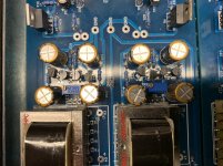
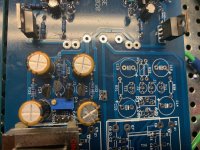
I compared resistors to schematic, measured spares of the same value and put them next to the ones on the boards to visually confirm they're right.
R26 = 100k
R28 = 330R
R30/31 = 8k2All good.
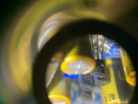
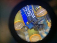
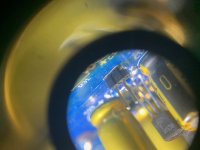
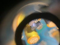
I checked to make sure transistors were in correct locations and orientations. See pix using loupe over iphone camera. All of that looks good.
Measurements:
BC546 & BC556 Base Voltage = +/- 14.69V
JP2 Pin 2 = -0.4mV (got a little drift..., need to tweak again)
JP2 Without jumper, power off:
Pin 1 to gnd 27.3 Ohms
Pin 2 to gnd 17.87k Ohm
Pin 3 to gnd 54.6 Ohm
WIP.R (input +) to gnd 55 Ohm
CCW.R (input -) to gnd 0 Ohm
Since I'm going fixed gain and no selection, I'm using the following:
Input + = WIP.R
Input - = CCW.R
Output + = OUT.R
Output - = OUT.R.GND
Thoughts? Will other pix or measurements be helpful?
Side note: my wife saw my schematic with marks from the build, and notes from troubleshooting next to my computer when I'm starting my work day. She said "That doesn't look like work". A few moments later she said, "That looks like fun!". I reminded her that from now on I can quote her saying audio circuits are considered fun to her based on her statement!
Before and after buffer voltage is same - so unity gain. See scope pic. Values dance a little on the scope, .918V, .923V, .945V, etc.
I'm getting good +/- 15V from PSU.
All boards perform the same, so I assume when I find the gremlin once, I'll be fixing it 4 more times. I started with the 1 channel board so it's easier to investigate.
I'm assuming PSU is good based on good +/-15V readings. So I'm focusing from signal input to output.
I compared resistors to schematic, measured spares of the same value and put them next to the ones on the boards to visually confirm they're right.
R26 = 100k
R28 = 330R
R30/31 = 8k2All good.
I checked to make sure transistors were in correct locations and orientations. See pix using loupe over iphone camera. All of that looks good.
Measurements:
BC546 & BC556 Base Voltage = +/- 14.69V
JP2 Pin 2 = -0.4mV (got a little drift..., need to tweak again)
JP2 Without jumper, power off:
Pin 1 to gnd 27.3 Ohms
Pin 2 to gnd 17.87k Ohm
Pin 3 to gnd 54.6 Ohm
WIP.R (input +) to gnd 55 Ohm
CCW.R (input -) to gnd 0 Ohm
Since I'm going fixed gain and no selection, I'm using the following:
Input + = WIP.R
Input - = CCW.R
Output + = OUT.R
Output - = OUT.R.GND
Thoughts? Will other pix or measurements be helpful?
Side note: my wife saw my schematic with marks from the build, and notes from troubleshooting next to my computer when I'm starting my work day. She said "That doesn't look like work". A few moments later she said, "That looks like fun!". I reminded her that from now on I can quote her saying audio circuits are considered fun to her based on her statement!
Attachments
Last edited:
if you have same signal level on input and output of buffers (shorting pins- easiest to get with probe) , than you're good with buffers
now - take ohmmeter , nothing connected to output, off state
do you have approx 100R from output hot to gnd ?
if yes autoformer is in continuity
if not, I ooked one trace - that one connecting pin 5 and pin 8 of CMOQ ; if that's the case, take a look at last picture for clue where and how and solder thin wire between pins 5 and 8
I wrote that already - somewhere along development of Iron Pre , I had a misfortune of broken consistency between board and schematic files ( sudden failure of damn HDD under waranty) , while being too deep in , to start from scratch
from that moment, I'm making it more or less with one eye patched , and with third eye looking at my back side
that's why you guys are making these beta builds, if not for other reason
Last edited:
Is the arrival of the Iron Pre in the store have an approximate time line yet, or still being worked out? Guess I could go ahead and order quad of Cinemag.
Speaking of Cinemag, it seems like I remember in some thread gentleman at Cinemag recommending the low iron version?
Also a couple sets of matched Toshiba Jfets from Punkydawgs. I have a stash of them (Toshiba) but as long as they are available (and more importantly, when spare play cash allows) I obtain a new set for new builds. I have enough for planned projects, but they do keep coming! (Thank goodness and thank you Mr Pass....)
I'm sure kit won't have J fets included (?) but possibly cinemags? if Iron will be in kit I could hold off for now. Guess it wouldnt hurt to have spare Cinemag in stash.
Balanced Iron Pre kits soon I hope.
Russellc
David @ Cinemag DID recommend to me the Low nickel version when I explained the project to him. We were discussing vinyl as source though...His belief was the Low nickel version would have more "warmth"—but it was also stated that it's completely subjective...try both and report back!
ZM stated that the Linear Sys Jfets in the store would work for Iron Pre (Post #1090)... Unless I'm reading that wrong.
I would imagine the store items will take time.........
I was texting with Jim 6L6 and then went down to investigate Jensen vs Cinemag traces. Here's what I find when I look for what traces are connected:
J1 - C5
J2/J3 - C3/C4
J4 - C2
J5 - C11
J6/J7 - C9/C10
J8 - C8
for now, most important is do you have that ~100R reading I said to check
- Home
- Amplifiers
- Pass Labs
- What's wrong with the kiss, boy?