With the test versions I've printed, the phase shield is always printed faulty. Decided to remove it in the end, because at least on the 4" version it makes a minimal impact and it's much easier to print without it.
If you are having problems with flush mounting elliptical waveguide, just make it have a round base with some free CAD program, such as TinkerCAD.
If you are having problems with flush mounting elliptical waveguide, just make it have a round base with some free CAD program, such as TinkerCAD.
Sorry. Apparently I wasn't clear. I'm talking about the, uh, business side of the waveguides. Your testing has shown a circular jig/mount into which the elliptical waveguides have gone.Not sure what you are asking for regarding a flat surface? The face the tweeter attaches to has some centering pegs which could be optional and a sealing lip which is not.
If I were mounting the 6" on a baffle, I'd like to be sure that the major axis is perpendicular to the vertical edge of the baffle (Y-axis) of the baffle. Looking at the template-making instructions on the Reddit link, below:
Step 2 - Creating X and Y coordinate lines is straightforward. I can probably eyeball the long axis using the side screw holes. Index marks on the back of the waveguide would be valuable to align the X and Y axes of the waveguide to the X and Y axes of the disposable first template.
Step 13 - this translates the patterning to the baffle, but it will also translate any initial positioning error (e.g., if the waveguide was canted 5 degrees when the first template was made, this is what would be transferred to the baffle).
Index marks on the back of the waveguide (voids, rather than protuberances would probably be easiest) would help align the guide. A flat surface, 90 or 180 degrees for an inch or so, would also help with alignment using a square (e.g., carpenter's, framing). Think of it like truncating a driver frame, but it doesn't have to be on the face of the WG (though that is easiest.
Thanks! I just re-read the thread and picked up on that. I'll just take the brute-force template approach, rather than trying for a generalized solution for ellipses. I'm not sure why using template making techniques isn't already in my go-to arsenal, but I'm sure it soon will be. Also, this is the upside for having spare junk parts. I don't have to worry about hurting them cosmetically.These are easy to make a routing template for: Tutorial: How to flush-mount irregular shaped speakers : diyaudio
")
Last edited:
Hey Brandon -
Have you done any modeling or fabrication for ribbons or AMT tweeters?
I've got some Airborne AMT tweeters that should work great in a WG, but no commercial product seems available.
If there is a model, I've got a friend with a 3d printer that has offered to print me some.
Thanks
Have you done any modeling or fabrication for ribbons or AMT tweeters?
I've got some Airborne AMT tweeters that should work great in a WG, but no commercial product seems available.
If there is a model, I've got a friend with a 3d printer that has offered to print me some.
Thanks
I haven't, but if you get me the relevant measurements I can see what I can come up with.
I'll provide physical measurements to the best of my ability.
Next few days....
Brandon,
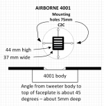
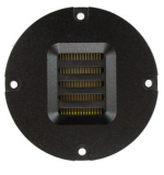
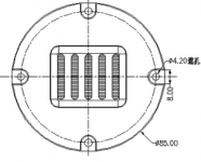
here is what the Airborne 4001 looks like, and I measured the dimensions as best as I could. No hurry on any sims, but I will try to respond quickly if you need more info.
THANKS!
here is what the Airborne 4001 looks like, and I measured the dimensions as best as I could. No hurry on any sims, but I will try to respond quickly if you need more info.
THANKS!
Attachments
Last edited:
Hey Brandon -
Have you done any modeling or fabrication for ribbons or AMT tweeters?
I've got some Airborne AMT tweeters that should work great in a WG, but no commercial product seems available.
If there is a model, I've got a friend with a 3d printer that has offered to print me some.
Thanks
You might like this:
Ribbon Unity Horn
This is a really some impressive work!
@Augerpro: Could you please share the stl/step for the SB19 WG? The SB19 is interesting because it is approx. ½ the price of the SB21.
Could you elaborate / summerize a litte on the geometry parameters for the different waveguide geometry parameters. eg. radius /ellipse parameters?
@Augerpro: Could you please share the stl/step for the SB19 WG? The SB19 is interesting because it is approx. ½ the price of the SB21.
Could you elaborate / summerize a litte on the geometry parameters for the different waveguide geometry parameters. eg. radius /ellipse parameters?
Some Christmas gifts for y'all! .stl files for the better performers so far.
SB26: 4" waveguide vA
Dropbox - 4x.625 A 67 SB26 v2.stl

SB26: 5" waveguide vG
Dropbox - 5x.75 G v5.stl

SB26: 8" waveguide vC
Dropbox - 8x1.5 C v3.stl

CSS LD22: 5" waveguide vB
Dropbox - 5x.75 B LD22 v2.stl

CSS LD22: 4" waveguide vA
Dropbox - 4x.625 A 67 LD22 v3.stl

SB21: 5" waveguide vB
https://www.dropbox.com/s/9s6jjkovsxugaxz/5x.75 B SB21 v1.stl?dl=0

SB21: 4" waveguide vA
https://www.dropbox.com/s/nxuqoaminmuuphy/4x.625 A 67 SB21 v1.stl?dl=0

SB26: 4" waveguide vA
Dropbox - 4x.625 A 67 SB26 v2.stl
SB26: 5" waveguide vG
Dropbox - 5x.75 G v5.stl
SB26: 8" waveguide vC
Dropbox - 8x1.5 C v3.stl
CSS LD22: 5" waveguide vB
Dropbox - 5x.75 B LD22 v2.stl
CSS LD22: 4" waveguide vA
Dropbox - 4x.625 A 67 LD22 v3.stl
SB21: 5" waveguide vB
https://www.dropbox.com/s/9s6jjkovsxugaxz/5x.75 B SB21 v1.stl?dl=0
SB21: 4" waveguide vA
https://www.dropbox.com/s/nxuqoaminmuuphy/4x.625 A 67 SB21 v1.stl?dl=0
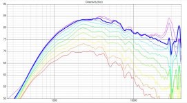
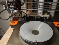
I did some waveguide printing this week and today some hands on testing as well. This is largely inspired by Brandon's efforts - so a huge thanks to him.
The driver: BlieSMa T34B-4
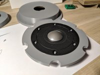
Waveguide: 165mm diameter - profile is a section of a radius of bigger circle. Printed on Prusa i3 MK2.5 - 0.2mm layer with linear advance, material PETG
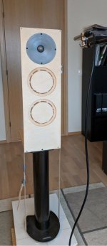
Test baffle - 220mm x 700mm baffle as intended for the final project (2.5way with 2x Satori MW16P)
Test conditions:
Mic to baffle distance for off axis measurements: 600mm
The driver: BlieSMa T34B-4
Waveguide: 165mm diameter - profile is a section of a radius of bigger circle. Printed on Prusa i3 MK2.5 - 0.2mm layer with linear advance, material PETG
Test baffle - 220mm x 700mm baffle as intended for the final project (2.5way with 2x Satori MW16P)
Test conditions:
Mic to baffle distance for off axis measurements: 600mm
Attachments
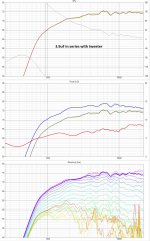
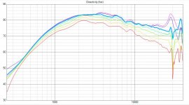
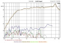
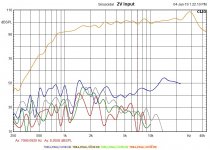
In addition two THD measurements
Mic to baffle distance for THD: 315mm
I tried to keep plots comparable to the hificompass.com test
*****
All in all, not a bad result for a first attempt to find a profile for this huge dome tweeter. I will try to print a phase shield out of interest too. There is a small dimple at 7.6k that could maybe be improved a bit, but not sure yet if it is that or might it be also the baffle edges as I'm using a realistic baffle not a huge IEC type baffle here.
Attachments
.stp files for CNC:
Dropbox - 4x.625 A 67 SB26 v2.step
Dropbox - 5x.75 G v5.step
Dropbox - 8x1.5 C v3.step
Dropbox - 5x.75 B LD22 v2.step
Dropbox - 4x.625 A 67 LD22 v3.step
https://www.dropbox.com/s/silchhoglo6kvr6/5x.75 B SB21 v1.step?dl=0
https://www.dropbox.com/s/gus68aa7h4havvn/4x.625 A 67 SB21 v1.step?dl=0
The last two are the SB21, not sure why the link looks like that.
By the way Brandon - do you normalize the measured curve levels around 1.2k? One aspect where our plots differ is that mine show some beaming effect already at 1k while yours match at that frequency for all angles. I could process my data same way if thats the case.
I did rotate around the vertical center axis of the front panel.
I did rotate around the vertical center axis of the front panel.
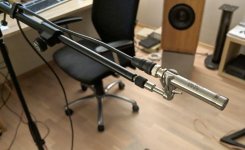
At 7khz you shouldn't see much baffle diffraction showing up with that design. I assume you are using a calibrated mic? My next guess would be the mic holder, if you have one of those typical saddle shaped ones it will reflect back to the mic tip, which shows as ripple in exactly this area.
By the way Brandon - do you normalize the measured curve levels around 1.2k? One aspect where our plots differ is that mine show some beaming effect already at 1k while yours match at that frequency for all angles. I could process my data same way if thats the case.
I did rotate around the vertical center axis of the front panel.
Your waveguide is bigger than most of the ones I've done, so that will show up on the low end by how much baffle diffraction starts to creep in. Plus my baffle is approx. 1.2m x 1.7m, so that diffraction shape will differ between us too.
At 7khz you shouldn't see much baffle diffraction showing up with that design. I assume you are using a calibrated mic? My next guess would be the mic holder, if you have one of those typical saddle shaped ones it will reflect back to the mic tip, which shows as ripple in exactly this area.
Thats a worthy to check idea. I'll experiment with some foam collar on it tomorrow.... it should be quite ok though and the mic itself is known to be flat there and I do use the cal curve yes. Though this one is pretty good to beyond 20k even without the cal file
Attachments
- Home
- Loudspeakers
- Multi-Way
- Open source Waveguides for CNC & 3D printing!