What's the crossover? I would be inclined to use the 4", and maybe the SB21 (unless you really want a metal dome).
Thing is, I already have 4x SB26ADC for the project. Mainly love them for the ultra-low distortion and low resonant frequency they have. I am aiming for keeping crossover points quite low, so drivers are within 1/4 wavelength of each other, creating a virtual point source. As so, I am aiming for 250 Hz & 1kHz crossover points. Of course, it depends on how the drivers measure in the prototype enclosure which will soon be printed. They are should be able to work as nearfield monitors as well aside from far-field listening.
The 4" waveguide would free much needed enclosure space for the bass driver. If you post the .stl files I can try it on as well. Is it possible for you to make the dimensions in millimeters?
The 4" waveguide would free much needed enclosure space for the bass driver. If you post the .stl files I can try it on as well. Is it possible for you to make the dimensions in millimeters?
Last edited:
A smokin' tweeter for a wg would be the D2604 series. With an FS around 500, they are awesome candidates. At reasonable volume in a medium or small room you could pull off 1,250 with one.
Problem with D2604 (both the silk dome and the ring radiator), is that while they have very low fs, their distortion starts rising before it. Of course the waveguide helps by providing gain, which combined with proper crossover can achieve a lower distortion result. Take at look at the D2604 distortion measurement from Voice Coil:
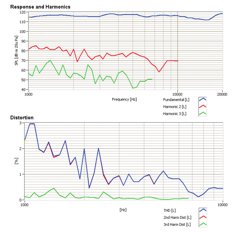
Whilst the SB26ADC keeps an ultra-low distortion up to around 1kHz. See measurement from Troels:

Whilst the SB26ADC keeps an ultra-low distortion up to around 1kHz. See measurement from Troels:
my money is on sb26 because of bigger xmax, but it needs its fs notched out.
otoh, d2608 hds due to ample copper and ferrofluid is very nice in virtually all waveguides with simple crossover.
otoh, d2608 hds due to ample copper and ferrofluid is very nice in virtually all waveguides with simple crossover.
The 4" waveguide would free much needed enclosure space for the bass driver. If you post the .stl files I can try it on as well. Is it possible for you to make the dimensions in millimeters?
Interesting idea! I'll try post the 4" tonight. And yes I can convert to mm for you.
Interesting idea! I'll try post the 4" tonight. And yes I can convert to mm for you.
Thanks! I'll post pictures when I have modified the waveguide to fit the enclosure. With the current 6" WG, it is a very tight fit.
I don't argue that the D2604 is an excellent driver, and the waveguide performance in there is superb. However, like I stated, the level of performance is acquired with proper waveguide along with proper crossover/EQ. The SB26ADC on the other hand, shows lower distortion even as bare driver without waveguide. It does require more EQ though, which is not a problem when using DSP.
If the conditions were comparable (and assuming the curves show D2 and D3) I would say that the D2604 has better distortion result from these measurements.Problem with D2604 (both the silk dome and the ring radiator), is that while they have very low fs, their distortion starts rising before it. Of course the waveguide helps by providing gain, which combined with proper crossover can achieve a lower distortion result. Take at look at the D2604 distortion measurement from Voice Coil:
Whilst the SB26ADC keeps an ultra-low distortion up to around 1kHz. See measurement from Troels:
1. The D2604 is measured at about 5 dB higher level.
2. The D3 is more important than D2 and is for the D2604 about 10 dB lower than for the SB26ADC.
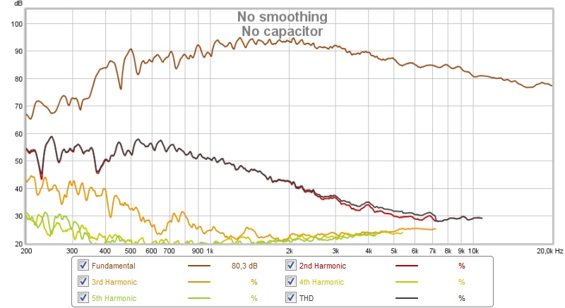
I've played around with a waveguide for the R2604/8330 and here is distortion for a large waveguide at 1 m:
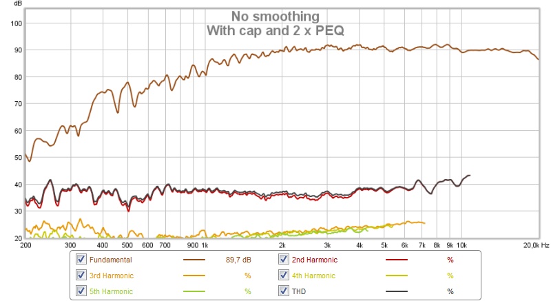
And with an added 10 uF cap, at 90 dB:
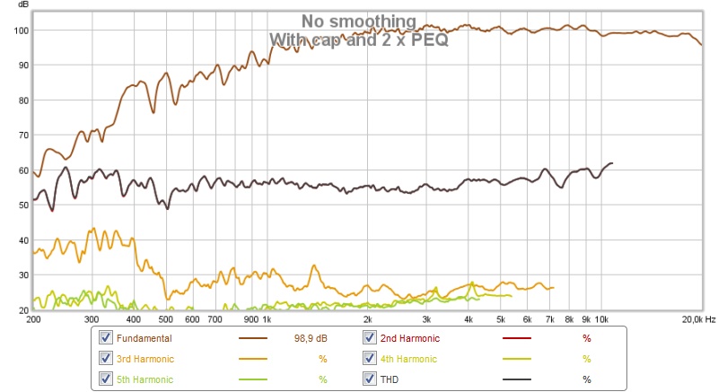
And at 100 dB:
The 3rd harmonic is impressively low. Not saying the SB26ADC is bad though, just that the interpretation of the data felt off.
/Anton
Troels even says that you may replace r2904 revelator with r2604....
But imho, i think he was more impressed with his sb26adc.
"The R2904/700000 tweeter is not exactly cheap and you may start out with the R2604/832000 tweeter if budget is tight...
...The R2904/700000 and R2604/832000 are so alike that only minor changes to the crossover is needed and the exceptional linear response from both tweeters on this baffle allows very simple crossovers. "
But still, i'm not building on industrial scale, life is short, and satori is definitely best bang for buck out there... thats why im still dreaming of a waveguide to match mr16p
The 3rd harmonic is impressively low.
Yes. 3rd, 4th and 5th are less than 0.1%, and I would not be surprised these results were dominated by the residual distortion of the measurement microphone or even the USB audio interface. What equipment did you use for this measurement?
Truly impressive results. Easy to cross around 1,5k.And with an added 10 uF cap, at 90 dB:
And at 100 dB:
We will have to wait until test print is complete (when I get all of the connectors and can measure exact diameter for the model) to see how the SB26ADC does. I expect to post some very low distortion numbers 🙂
I'm well aware of the merits of the SB product: my last three speaker builds have used them: this is the LCR setup in my movie room:

Testing the left.....

As it stands, I plan on using an SB driver for both tweeter and woofer in this build 😉
Testing the left.....
As it stands, I plan on using an SB driver for both tweeter and woofer in this build 😉
This is true, noise floor is around 30 dB.Yes. 3rd, 4th and 5th are less than 0.1%, and I would not be surprised these results were dominated by the residual distortion of the measurement microphone or even the USB audio interface. What equipment did you use for this measurement?
Umik-1 was used together with a laptop, nanoAVR and irs2092 amp.
/Anton
Thanks! It's a very large waveguide though, that then got synergized. I really liked the results, best speaker I've made.Truly impressive results. Easy to cross around 1,5k.
We will have to wait until test print is complete (when I get all of the connectors and can measure exact diameter for the model) to see how the SB26ADC does. I expect to post some very low distortion numbers 🙂
Synergy attempt without compression driver
/Anton
The 4" waveguide would free much needed enclosure space for the bass driver. If you post the .stl files I can try it on as well. Is it possible for you to make the dimensions in millimeters?
Dropbox - 4x.625 A SB26 v2.stl
Thanks Brandon!

Here is the measured response of the 4" waveguide.
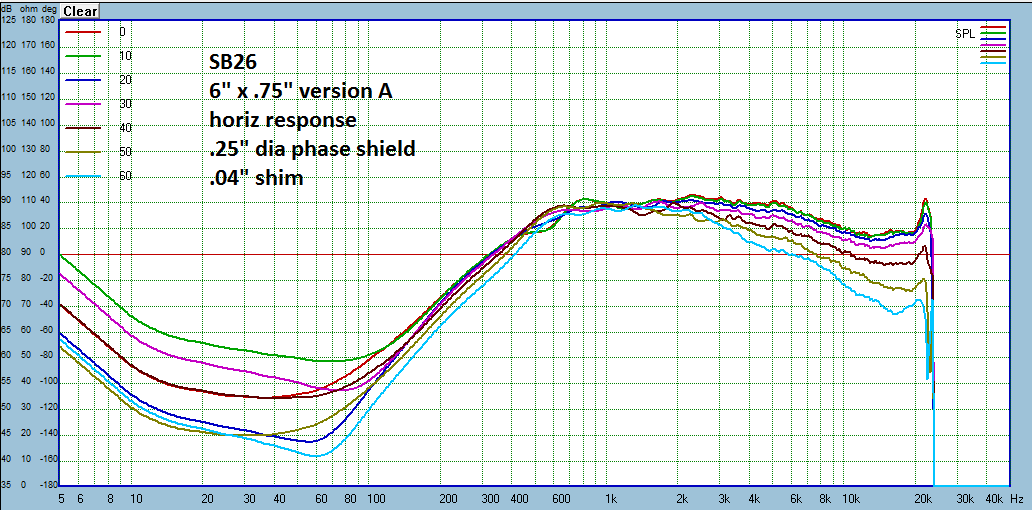
Here is the measured response of the 6" waveguide.
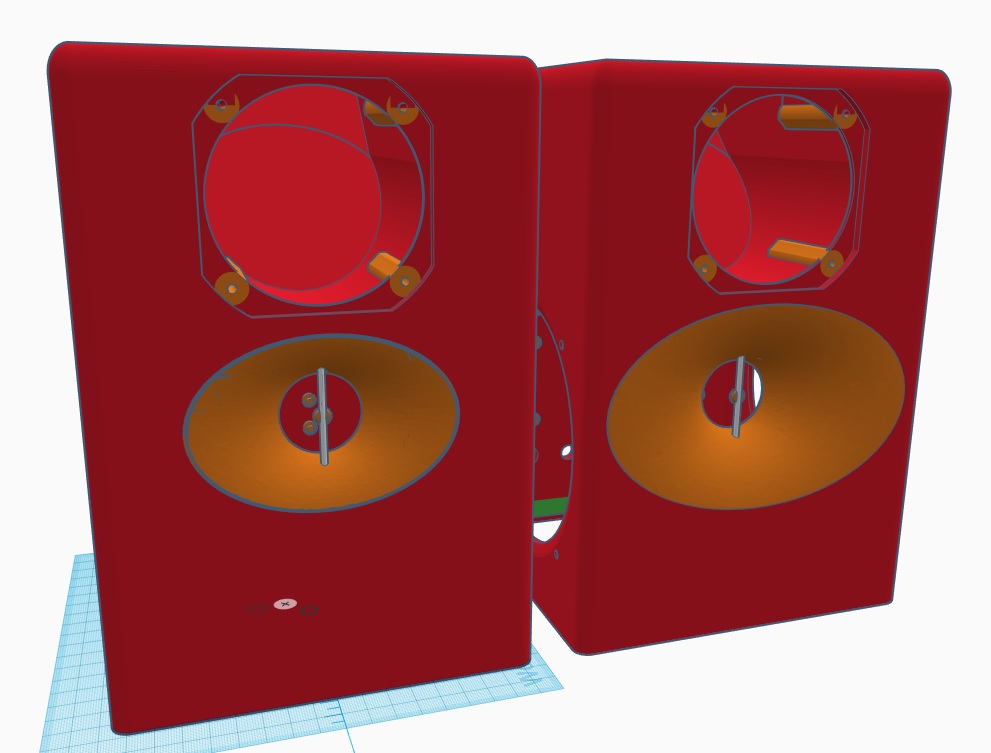
Here they are side by side on my project model. With the 4" waveguide, the CTC distance between mid and tweeter is 86mm, which is the 1/4 wavelenght for 1kHz crossover point. Below this point, tweeter and mid function as a point source. Another upside is increased enclosure volume, which will ease some load off the woofer. The design is extremely compact, only 250mm high, 170mm wide, 153mm deep.
Here is the measured response of the 4" waveguide.
Here is the measured response of the 6" waveguide.
Here they are side by side on my project model. With the 4" waveguide, the CTC distance between mid and tweeter is 86mm, which is the 1/4 wavelenght for 1kHz crossover point. Below this point, tweeter and mid function as a point source. Another upside is increased enclosure volume, which will ease some load off the woofer. The design is extremely compact, only 250mm high, 170mm wide, 153mm deep.
Attachments

Hmmm, I'm not sure if the if the waveguide response will smoothly become the baffle response below the waveguide "cut-off". On pro horns there is actually a large widening in the dispersion just below cutoff which then becomes the baffle response a little farther down. Might be worthwhile to build a mockup and see how it measures.
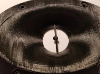
I tried getting the 6" G version printed on a 100um PETG process through 3DHubs, but the service provider wanted to make unspecified changes to reinforce the part -- at an upcharge, of course. So, I went with a 200um process, and I'm skeptical that it's usable -- too much striation. But the build quality is fine, so my skepticism of the 100um guy's proposed changes seems well founded.
I went back into the site yesterday to see if I could find a higher-resolution print option at an affordable price. With yesterday's pricing, a resin print at 25um was less than the original quote for 100um PETG (~$140 vs. ~$160 for two pieces). Also noteworthy: the upcharge for shifting from a 100um process to a 25um process was $6, but the upcharge to go from 100um to 50um was more than $10. So the 25um print was cheaper than a 50um print.
Net-net: 3DHubs is gig work for guys with printers, so you may need to play around with the various options on different days to get the right combination of process, price and provider (how's that for alliteration? :-o).
Even though I've got a low quality print in-hand, I'd make a suggestion for improvement:
It would be nice to have flat surfaces (rear flange?) to use so that one can square the ellipse to the baffle for those of us going the "print" route.
Also, any tips/tricks for mounting are appreciated. I haven't found a commercially-available ellipse jig that a) works at this small of a scale, and b) that fits one of my routers. I may have to trace my dummy part and free-hand the cut, but I'd prefer that as a last resort if there are better options.
Attachments
Last edited:
Not sure what you are asking for regarding a flat surface? The face the tweeter attaches to has some centering pegs which could be optional and a sealing lip which is not.
These are easy to make a routing template for: Tutorial: How to flush-mount irregular shaped speakers : diyaudio
These are easy to make a routing template for: Tutorial: How to flush-mount irregular shaped speakers : diyaudio
- Home
- Loudspeakers
- Multi-Way
- Open source Waveguides for CNC & 3D printing!