Do you have one to listen in?
Yep, and it's the biggest room in my house....i call it the 'outsideroom'
But kidding aside...as you know, i do like to adjust FR outdoors as flat as possible (mag and phase), as a 'best effort' quasi-anachoic tuning.
Then, when i move in to a room, i like to use the impulse response to find and treat reflections.
And use RT60 to even room reverb.
That done, I don't like to use any further EQ for speaker tuning, other than maybe a little parametric for knocking down room modes
(which i tend to think of as room tuning as opposed to speaker tuning, more similar to reflections, RT60, absorption/diffusion, etc)
All that said, i find great use for EQ in setting listening preferences, via a static house curve , and also for on-the-fly track-by-track tonal adjustments.
Just my way of trying to separate variables and address them, in a way that seems logical to me at least..
Whatever works best for us, huh?
The separate EQ banks in rephase are a great boon to splitting out EQ tasks imo/ime. (other than on-the-fly of course).
That's one advantage of active IIR over FIR we almost never hear discussed, the difficulty to make real time adjustments with FIR.
Last edited:
Hello emailtim
rePhase is agnostic to the measurement process itself, so any specific rule regarding measurement will have to do with the measurement software itself (things like sampling rate, calibration, gating, etc.).
The higher the measurement sampling rate the larger the bandwidth on which you will be able to see the result of your correction, but 48kHz is enough for any practical purpose here. This is only a visual clue.
In any case the measurement sampling rate (and other parameters) has no relation with the FIR sampling rate. You can even build your FIR without relying on any measurement.
Thanks for the information, very helpful.
I have been looking for a clear manual to use REW+rephase to build a fully digital 2X4-way crossover to implement using the built-in convolver in Jriver. Alas, I cannot find step-by-step directions to do that after extensive searching. Any pointers will be much appreciated. To be sure I have gone though the tutorials on rephase.org, and http://jimmy.thomas.free.fr/Jriver/Tuto-Jriver-RePhase-HolmImpulse.pdf. It appears for someone looking into this for the first time, a "cookbook" would be super helpful, starting with measuring individual drivers in REW, and going from there to generate a full crossover. For now, I am totally clueless. The extent of my skills is limited to generating full sweep measurements of my active 2X4-way system (I use a minidsp 2x10hd) and correcting response peaks. I want to experiment with replacing the entire crossover with FIR+IIR filters and run them within Jriver via a 8 channel USB dac.
Last edited:
All of the steps you mention are individual and unless someone has done exactly what you want to do it is hard to get a full step by step list of instructions, and even if you got them the results might not be what you expected.
Learning to measure a speaker correctly does take some trial and error and experience and is not that easy to condense into a one liner due to all the variables involved.
My advice is to look into Vituixcad, there is a very extensive guide on how to measure and get the raw data you need there. You can use it create your crossovers and simulate the result. You can take that and create those crossovers with rephase.
To get multichannel convolution going in Jriver needs a configuration file plenty of information available on how to do that.
If you want an integrated solution that does it all for you then look at Acourate or Audiolense they can do it all for you by selecting the options you want, generate the convolution files and a configuration for use. You just have to pay the price for someone to have put it all together for you.
Mitch Barnett has written a few articles at Audiophile style / Computer audiophile that run through using those programs, well worth reading in any case.

I’m back , got another question for the experts
How does a linearized filter or a linear phase filter compare to the minimum phase filter
As far as crossover transient response?
Sorry I’m not good at calculating vectors or any math riddled equations, as I am a math dummy.
Just wondering if either method of crossover implementation via rephase does any thing to transient response.
I’ve recently found a new love for the LR2 and have a curiosity itch
Much appreciated,
Andrew
Hello Andrew,
Assuming proper acoustical crossover layout in both cases (complementarity, phase tracking), a minimum-phase crossover will have post ringing at the crossover frequency, whereas a linear-phase (or linearized) one will have no ringing at all at that frequency (ie seamless crossover, as if only one driver was playing).
Now in a real world situation this only happens on axis with non-coincident drivers of different sizes.
Off axis (especially vertically) summation will not be perfect and in that case both crossovers will present some amount of ringing at the crossover frequency, with more pre ringing for the linear-phase version.
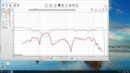
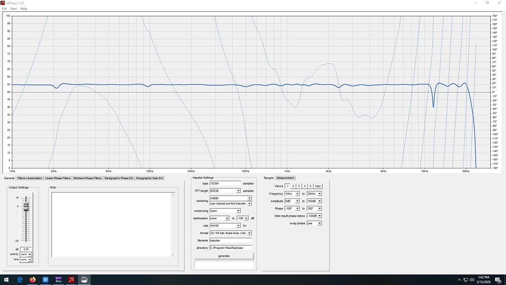
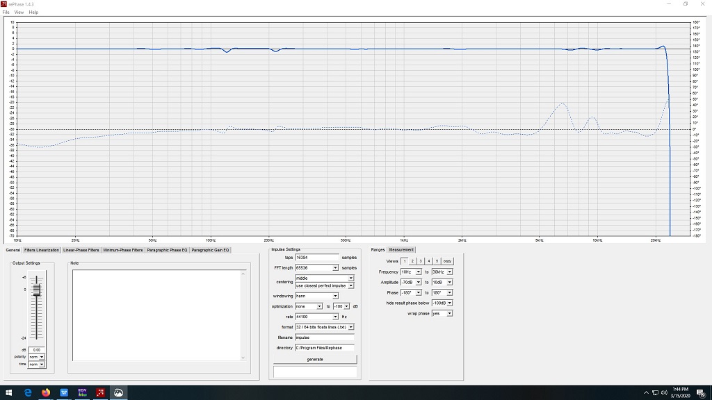
I'm working through SwissBear's 'REW measurement averaging + Rephase' tutorial and my progress has stalled on the last couple of pages.
As seen here I've reached the point where the amplitude correction impulse is ready to be applied to RAvg as seen here.
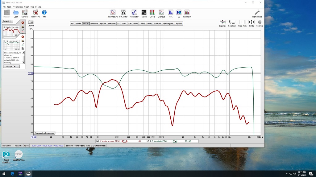
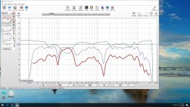
The next photo shows the the creation of A*B with the SPL adjusted down 70db to show in the graph.
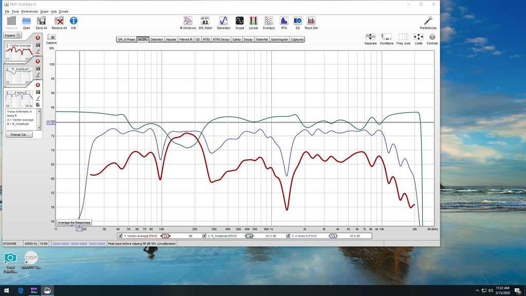
Next we see A*B by itself.
And finally all four together.
Give me a couple more minutes and I'll post my Rephase results to see if I'm on the right track.
Regards,
Dan
As seen here I've reached the point where the amplitude correction impulse is ready to be applied to RAvg as seen here.
The next photo shows the the creation of A*B with the SPL adjusted down 70db to show in the graph.
Next we see A*B by itself.
And finally all four together.
Give me a couple more minutes and I'll post my Rephase results to see if I'm on the right track.
Regards,
Dan
Attachments
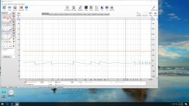
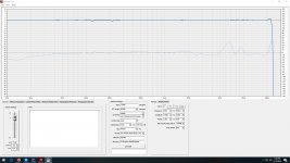
Anyways, here's my Rephase results
What throwing a monkey into my wrench is SwissBear's quote from his 2017 article titled, "Acoustic treatment & Calibration
Rephase - The Tutorial
[pda0] & [Bear]"
And, in the same tutorial he mentions A+B which appears to produce better results for me?
Regards,
Dan
What throwing a monkey into my wrench is SwissBear's quote from his 2017 article titled, "Acoustic treatment & Calibration
Rephase - The Tutorial
[pda0] & [Bear]"
Note: the measurement of the left channel must be without windowing, otherwise the operation will be incorrect. So make sure
that the windowing is removed (box unchecked on the IR window). We choose the operation A * B and press the generate
button.
And, in the same tutorial he mentions A+B which appears to produce better results for me?
Regards,
Dan
Attachments

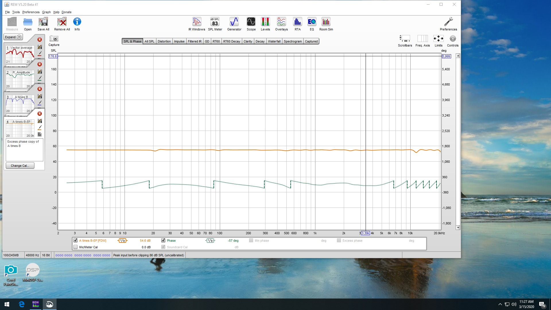
What that means is that you need to convolve the correction with an un-windowed raw measurement. If you perform trace arithmetic in REW or export the measurement, the FDW can become baked into the response.
So deselect the FDW in the IR window before performing trace arithmetic on the measurement. You can always put it back on for viewing afterwards.
A*B with a level reduction is the correct way of convolving traces together in REW.
A+B is adding the responses together, that is for two sides of a crossover or similar applications.
This is simulating a convolution so A*B is right.
The orange trace is your excess phase which you imported into rephase. The filter generated from that needs to be imported into REW and convolved (A*B) with the other traces to get the overall result.
Your vector average is a bit strange, that is a big dip at 1.5K. Without knowing more about your speakers or room it is hard to guess what is happening.
Question about RIAA EQ with Rephase.
I would like to do RIAA EQ via convolution using rephase. I searched around and noticed some old posts from POS about adding RIAA EQ into rephase as a "standard filter" but as far as I can see it never happened. Is there a reason it didn't happen (like it doesn't work) or something else. I also see several different RIAA solutions posted but little follow up if these work correctly or not. Any help / advice on RIAA EQ with rephase appreciated
I would like to do RIAA EQ via convolution using rephase. I searched around and noticed some old posts from POS about adding RIAA EQ into rephase as a "standard filter" but as far as I can see it never happened. Is there a reason it didn't happen (like it doesn't work) or something else. I also see several different RIAA solutions posted but little follow up if these work correctly or not. Any help / advice on RIAA EQ with rephase appreciated
Question about RIAA EQ with Rephase.
I would like to do RIAA EQ via convolution using rephase. I searched around and noticed some old posts from POS about adding RIAA EQ into rephase as a "standard filter" but as far as I can see it never happened. Is there a reason it didn't happen (like it doesn't work) or something else. I also see several different RIAA solutions posted but little follow up if these work correctly or not. Any help / advice on RIAA EQ with rephase appreciated
Hi levimax,
Here are the correct settings for RIAA Playback curve in rePhase…
Just apply these 3 simple filters using the "Minimum-Phase Filters" tab:
NORMAL --- LOW-PASS --- 1st order --- 2122 Hz
COMPENSATE --- HIGH-PASS --- 1st order --- 500 Hz
NORMAL --- HIGH-PASS --- 1st order --- 50 Hz
Equally valid, the filter shape name "1st order" could also be set to "Butterworth" with "6 dB/oct" slope which is exactly the same thing.
If you ever need to make the RIAA Recording curve (perhaps if you were mastering to a vinyl cutting lathe machine???), which gives the opposite curve, just use the same settings above, but for each filter swap NORMAL to COMPENSATE or vice versa, to invert their behaviour.

https://www.diyaudio.com/forums/att...ation-eq-fir-filtering-tool-riaa-settings-jpg

https://www.diyaudio.com/forums/att...rization-eq-fir-filtering-tool-riaa-graph-jpg
Last edited:
Hi levimax,
Here are the correct settings for RIAA playback curve in rePhase…
Apply 3 simple filters using the "Minimum-Phase Filters" tab:
NORMAL --- LOW-PASS --- 1st order --- 2122 Hz
COMPENSATE --- HIGH-PASS --- 1st order --- 500 Hz
NORMAL --- HIGH-PASS --- 1st order --- 50 Hz
(NB: Alternatively, filter shape "1st order" could equally be set to "Butterworth" with "6 dB/oct" slope which is exactly the same thing.)
View attachment 825480
https://www.diyaudio.com/forums/att...ation-eq-fir-filtering-tool-riaa-settings-jpg
View attachment 825479
https://www.diyaudio.com/forums/att...rization-eq-fir-filtering-tool-riaa-graph-jpg
Thank You!!
What that means is that you need to convolve the correction with an un-windowed raw measurement. If you perform trace arithmetic in REW or export the measurement, the FDW can become baked into the response.
So deselect the FDW in the IR window before performing trace arithmetic on the measurement. You can always put it back on for viewing afterwards.
A*B with a level reduction is the correct way of convolving traces together in REW.
A+B is adding the responses together, that is for two sides of a crossover or similar applications.
This is simulating a convolution so A*B is right.
The orange trace is your excess phase which you imported into rephase. The filter generated from that needs to be imported into REW and convolved (A*B) with the other traces to get the overall result.
Your vector average is a bit strange, that is a big dip at 1.5K. Without knowing more about your speakers or room it is hard to guess what is happening.
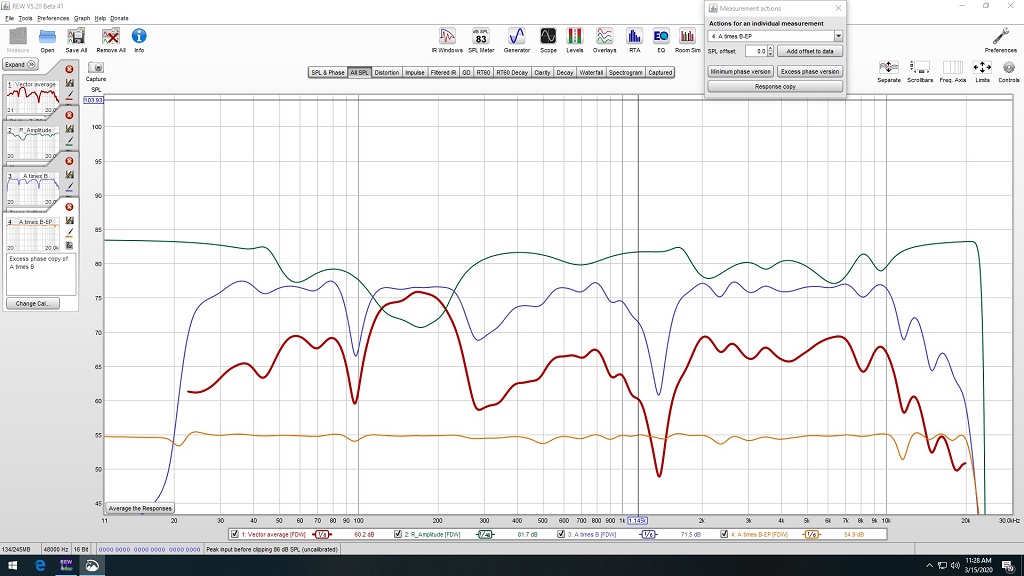
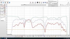
Ok, Here we go!
Red is the sum of the 9 left channel measurements without FDW.
Green is the amplitude correction impulse imported from Rephase.
Blue is A*B of the above.
More when I do a bit more reading.
Regards,
Dan
Attachments
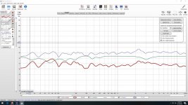
On your Red Average line try setting REW's auto EQ reference at about 68dB and run it again to see what it comes up with the EQ on your graph looks odd which is why the A*B is not very flat.
Your graph as it is now will most likely sound bright as a flat power response in room does not sound flat.
Your graph as it is now will most likely sound bright as a flat power response in room does not sound flat.
- Home
- Design & Build
- Software Tools
- rePhase, a loudspeaker phase linearization, EQ and FIR filtering tool