Hi Pos,
I did follow the instructions for using the compensate filters to flatten the response first. Then i apply the desired electrical crossover say LR4 (linear phase). however the final acoustic response curve doesn't have an LR4 slope.
Hi jojip,
If the final curve does not fit then something is amiss in either the first measurement (the one on which the rephase correction is based) or the second one.
It is almost impossible to get an accurate measurement on a large frequency range, and you typically have to play with the measurement window length and/or mic distance to get an accurate measurement of the lower part or the higher part of the range. A single measurement cannot do it most of the time.
For example shortening the measurement window will tend to reduce the slope of the high pass.
So the only solution is to use several measurements (or different windowed versions) and go from one to the other (the drag and drop functionality should reduce the pain) when addressing each part of the spectrum.
Yes of course.can multiple filters say high-pass, compensate be used simultaneously in the minimum-phase tab to flatten out the response?
There are several ways of using these functionalities.could you elaborate on using the inverse EQ method? Does it involve loading an inverse of the measured driver response (invert a measurement using REW or ARTA?) and use it as a target for the first filter. This filter is then followed by a second filter applying the desired electrical crossover. The acoustic slope should then match very closely.
What I was thinking about here is the case where you want to follow a given target response, either for a single river (LR, etc.) or a fullrange reponse (X-curve, etc.).
In this case instead of importing or modeling a given response curve and use it as a visual target, you can model it using EQs and filters and then "reverse" them (compensate mode for filters, and opposite dB values for EQs) and shoot for a flat response.
And then of course at the end you would have to remove those reverse EQ/filter points before generating the impulse...
Shooting for a flat response is much more precise than trying to follow a target, because you can use the zoom functionalities to their best.
I don't have that much examples to share.It would be great if you can post an example of an XO project you developed using rePhase. This can be a great user guide example for new users
I might share a project that I made with a member here to turn his JBL 4365 into an active system. This would require some time as we had to use multiple (a lot!) measurements...
Thanks Much Pos. I am trying to learn this, so pardon me if i appear a bit thick in the head.
My original intent was indeed to have a visual target reference of the desired acoustic response as i manually corrected the measured response using filters to match the reference.
Please clarify couple of things from your comment:
My read of this is, as one is developing the manual filters for a driver, load different measurements of the driver into the same rephase window to see the effect of the selected filters on the different measurements.
Makes sense.
Sorry but i am still missing this. When is the initial measured response loaded? Could you please provide an example when you get a chance?
My original intent was indeed to have a visual target reference of the desired acoustic response as i manually corrected the measured response using filters to match the reference.
Please clarify couple of things from your comment:
So the only solution is to use several measurements (or different windowed versions) and go from one to the other (the drag and drop functionality should reduce the pain) when addressing each part of the spectrum.
My read of this is, as one is developing the manual filters for a driver, load different measurements of the driver into the same rephase window to see the effect of the selected filters on the different measurements.
Makes sense.
In this case instead of importing or modeling a given response curve and use it as a visual target, you can model it using EQs and filters and then "reverse" them (compensate mode for filters, and opposite dB values for EQs) and shoot for a flat response.
And then of course at the end you would have to remove those reverse EQ/filter points before generating the impulse...
Shooting for a flat response is much more precise than trying to follow a target, because you can use the zoom functionalities to their best.
Sorry but i am still missing this. When is the initial measured response loaded? Could you please provide an example when you get a chance?
Hey guys,
I've read through the first 20 pages of the thread then the last 10 pages. I'm doing something very similar to jojip, also using JRiver, except I'm doing it in stages.
I just finished a pair of 10" mid bass I'm inserting between my sub(s) and a set of bookshelf speakers. After playing with my crossover points and slopes a little and adding some low shelf for baffle step compensation they are sounding pretty decent. I've just been doing it by ear so far but will take real measurements this weekend, following the tutorial on the JRiver forum.
For now though, is there any reason I shouldn't use rePhase to generate FIR filters matching the IIR filters I created so far in JRiver PEQ? I'm really wanting to remove the crossover phase shift and then do some time alignment with the greatest null thing to see how it sounds. My sub and mid bass enclosures are sealed so there shouldn't be much group delay from the box.
I was messing with it earlier, trying to create the bandpass filters for just this mid bass and trying to include some baffle step compensation at the same time.
Does what I have done below look reasonable? I just created the filters to match what I did in JRiver then I found the loudness preset which gave me a curve that looks close to what I want.
Am I messing anything up badly here?
Thanks,
Chris
Attachments
That is correct.My read of this is, as one is developing the manual filters for a driver, load different measurements of the driver into the same rephase window to see the effect of the selected filters on the different measurements.
Makes sense.
Sorry but i am still missing this. When is the initial measured response loaded? Could you please provide an example when you get a chance?
Sorry, my explanations were not very clear.
So let's imagine you want to do a global EQ of your speakers. You take a measurement and load it into rephase, then you EQ the thing to a flat target.
But depending on your measurement situation (distance, window) you might want to shoot for a non flat target (so called house curves).
Then you run another instance of rephase and model you target curve using EQ and/or filters, and you report it into your main instance with opposing settings (negative EQs and compensate filters), and once again shoot for a flat target.
Then you just have to remove those opposing settings and voilà, you have your correction.
Of course this can also apply for a single driver, etc.
Hey guys,
I've read through the first 20 pages of the thread then the last 10 pages. I'm doing something very similar to jojip, also using JRiver, except I'm doing it in stages.
I just finished a pair of 10" mid bass I'm inserting between my sub(s) and a set of bookshelf speakers. After playing with my crossover points and slopes a little and adding some low shelf for baffle step compensation they are sounding pretty decent. I've just been doing it by ear so far but will take real measurements this weekend, following the tutorial on the JRiver forum.
For now though, is there any reason I shouldn't use rePhase to generate FIR filters matching the IIR filters I created so far in JRiver PEQ? I'm really wanting to remove the crossover phase shift and then do some time alignment with the greatest null thing to see how it sounds. My sub and mid bass enclosures are sealed so there shouldn't be much group delay from the box.
I was messing with it earlier, trying to create the bandpass filters for just this mid bass and trying to include some baffle step compensation at the same time.
Does what I have done below look reasonable? I just created the filters to match what I did in JRiver then I found the loudness preset which gave me a curve that looks close to what I want.
Am I messing anything up badly here?
Thanks,
Chris
Hi Chris,
Good minimum-phase settings, such as the one you can do using the IIR filter in jriver, will shoot for a complementary acoustical crossover (LR for example). This means you will take the actual "natural" rolloff of the driver+box into account when creating the electrical filters and EQs, so that the two add up and end up being your acoustical target.
If you replace you minimum-phase filters with linear phase ones you will reach the same magnitude response, but the phase response will be different as even if you electrical filter do not add any phase shift the natural roll off of your driver+box still adds his.
One solution might be to linearize the phase of said natural filter.
Another option is to use the compensate mode to "delete" the natural filter and replace it with whatever filter you want, and your electrical filter becomes your acoustical one.
This second option has my preference, but both will require you to measure what is actually going on.
In the end doing a multiway linear phase filter is much easier than a minimum-phase one, because you don't have to take into account the influence of one crossover point of the others...
Still, with no measurement you are shooting in the dark. I don't say it cannot be done (I could not myself, but some probably can), but this is much more difficult that using good measurements.
One last thing regarding your screenshots.
When doing speaker correction you want to use minimum-phase EQs, because what you are correcting *is* a minimum-phase system.
There is basically zero situation (that I know of) were linear-phase EQ would be at an advantage there, unless you completely separate magnitude and phase EQ, but this not a really efficient way to do it...
Filters (when used in a crossover) are a different thing...
Thanks for the help, Thomas. I'm going to use HOLMImpulse to take real measurements starting tomorrow. I was just hoping I could take the IIR crossovers I have configured right now and duplicate them as FIR, to remove the phase shift caused by the crossovers.
I'm sure I will end up tuning what I created today to some degree but I don't expect them to be too far off. I started with 4th order LR (two 12 DB filters stacked in JRiver) filters everywhere and really didn't end up changing a lot other than remove the original high pass from the mid bass to let it roll off naturally, then add back a steeper filter at a lower frequency to keep cone excursion under control.
I know this isn't very accurate but I did watch the analyser window to see what was going to each channel around my crossover points. And I listened to music I know pretty well from a decent headphone setup. So I will be measuring and verifying but it's already pretty listenable.
I'm just excited to hear how much difference removing crossover phase shift and then time aligning will make.
I did plan to try correcting the passive crossover phase shift in the bookshelf speakers but read some of your comments about the mid to tweeter phase not being so audible. Luckily the bookshelf speakers are wired to allow bi-amping so I can measure the mids separately from the tweeters and hopefully the slopes will be clear.
-Chris
I did recreate my crossovers as linear phase yesterday but didn't try to include any slopes at the same time. Listening to it convoluted right now. I still haven't been able to measure my individual drivers as I had to order a microphone stand. But I've been learning a lot more about how to use different software tools, just from measurements at my listening position.
I'm still getting my head around what I should do with linear phase and what should be minimum phase.
I know linear phase is good for my actual crossovers.
But correcting driver response should be minimum phase so I think it would actually be just fine to do with IIR PEQ, which is much easier to tweak.
I think the response curve I'm applying with a low shelf should be done linear phase since it is pretty similar to crossovers.
But I'm not so sure about trying to level out peaks caused by room modes. It seems like linear phase EQ is the way to go there though.
Am I really off base with any of that? If not, how would I go about creating a house curve when I'm using 3 separate .wav files now and could even end up with a file per driver in the end? The low shelf I'm using right now spans half the midbass driver frequency range and all of the sub frequencies. I'm going to experiment with it but any advice would be much appreciated.
Thanks,
Chris
That is correct.
Sorry, my explanations were not very clear.
So let's imagine you want to do a global EQ of your speakers. You take a measurement and load it into rephase, then you EQ the thing to a flat target.
But depending on your measurement situation (distance, window) you might want to shoot for a non flat target (so called house curves).
Then you run another instance of rephase and model you target curve using EQ and/or filters, and you report it into your main instance with opposing settings (negative EQs and compensate filters), and once again shoot for a flat target.
Then you just have to remove those opposing settings and voilà, you have your correction.
Of course this can also apply for a single driver, etc.
Pos, thanks for the explanation. As i find time i will repeat some measurements and try these out.
Hi Pos, new poster to rePhase thread.
First, many thanks for your great program!!
I'd like to ask a few questions on how to use rePhase with my tuning project.
The project is a 3 way main speaker and ultimately aligned with horn loaded subwoofer. It's PA gear and I'm using a miniDSP OpenDRC DA8 and also a 2 channel DA, feeding into a X-32 rack mixer enroute to amps.
Measurements for import into rePhase have been made with smaart, outdoors, at a little over 2 meters. I've gone through driver by driver tuning per the instructions on the miniDSP site with fair success, but just recently found updated instructions such as your post #674 in this thread, and am now working with those.
Crossover points are: sub to MF @100hz, MF to HF @650hz, and and HF to VHF @6300hz. I'm currently using LR24 at 100, and LR48 at 650 and 6300
I was going to use the DA8 in a 2X3 configuration for the mains, but found I could not get as much phase flattening as I would like on the main MF section's 100hz crossover with the 2048 taps available in the DA8, so I am currently using the DA's 6144 taps for the MF, and the DA8 for HF and VHF.
So first questions....
I've read your posts to keep filter topology the same on both sides of x-over.
I don't think I need to be concerned with one side of x-over at 650hz using 6144 taps and the other 2048 taps, but I'm wondering if there are any special steps required other than time alignment. (I can do time alignment with either the mixer or DSP amps).
Also, I'm simply using a Y cable to feed the spdif coaxial inputs of the two miniDSP units...any prob there?
As far as sequence with rePhase... my understanding goes like...
1. use Paragraphic Gain(minimum phase) EQ to first flatten response in the passband
2. then use Minimum-Phase Filters 'compensate', and 'time offset' in measurement to flatten phase, and to continue flattening amplitude.
3. Apply Linear-Phase Filters
Q? #1 and #2 affect each other...I assume you just keep going back and forth?
Q? I'm trying to get amplitude and phase flat through the passband and beyond, at least to -15db corners. So far I have had to use Paragraphic-Phase EQ in addition, to do this. But I read in post 677 that I should never have to use phase EQ for individual drivers...
Am I giving up too soon, going to Phase Eq?
Do you use mulitple HP and LP compensations or something I'm missing?
Last Q?")
Regarding 'maximum response level' given under generate....
Does it need to stay below zero?
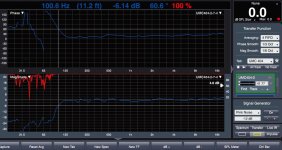
Again, thanks for a remarkable program...here's a transfer function from smaart when using 2048 taps for MF...been too windy yet,to measure 6144 tap try. I'm stoked how well your program works!
First, many thanks for your great program!!
I'd like to ask a few questions on how to use rePhase with my tuning project.
The project is a 3 way main speaker and ultimately aligned with horn loaded subwoofer. It's PA gear and I'm using a miniDSP OpenDRC DA8 and also a 2 channel DA, feeding into a X-32 rack mixer enroute to amps.
Measurements for import into rePhase have been made with smaart, outdoors, at a little over 2 meters. I've gone through driver by driver tuning per the instructions on the miniDSP site with fair success, but just recently found updated instructions such as your post #674 in this thread, and am now working with those.
Crossover points are: sub to MF @100hz, MF to HF @650hz, and and HF to VHF @6300hz. I'm currently using LR24 at 100, and LR48 at 650 and 6300
I was going to use the DA8 in a 2X3 configuration for the mains, but found I could not get as much phase flattening as I would like on the main MF section's 100hz crossover with the 2048 taps available in the DA8, so I am currently using the DA's 6144 taps for the MF, and the DA8 for HF and VHF.
So first questions....
I've read your posts to keep filter topology the same on both sides of x-over.
I don't think I need to be concerned with one side of x-over at 650hz using 6144 taps and the other 2048 taps, but I'm wondering if there are any special steps required other than time alignment. (I can do time alignment with either the mixer or DSP amps).
Also, I'm simply using a Y cable to feed the spdif coaxial inputs of the two miniDSP units...any prob there?
As far as sequence with rePhase... my understanding goes like...
1. use Paragraphic Gain(minimum phase) EQ to first flatten response in the passband
2. then use Minimum-Phase Filters 'compensate', and 'time offset' in measurement to flatten phase, and to continue flattening amplitude.
3. Apply Linear-Phase Filters
Q? #1 and #2 affect each other...I assume you just keep going back and forth?
Q? I'm trying to get amplitude and phase flat through the passband and beyond, at least to -15db corners. So far I have had to use Paragraphic-Phase EQ in addition, to do this. But I read in post 677 that I should never have to use phase EQ for individual drivers...
Am I giving up too soon, going to Phase Eq?
Do you use mulitple HP and LP compensations or something I'm missing?
Last Q?
Regarding 'maximum response level' given under generate....
Does it need to stay below zero?
Again, thanks for a remarkable program...here's a transfer function from smaart when using 2048 taps for MF...been too windy yet,to measure 6144 tap try. I'm stoked how well your program works!
Attachments
Hi Thomas,

it can be hard for a single driver (with limited bandwidth)
Why don't apply directly the target from an another instance,in a free bank (once the measurement is flattened) ?
Sorry, my explanations were not very clear.
So let's imagine you want to do a global EQ of your speakers. You take a measurement and load it into rephase, then you EQ the thing to a flat target.
But depending on your measurement situation (distance, window) you might want to shoot for a non flat target (so called house curves).
Then you run another instance of rephase and model you target curve using EQ and/or filters, and you report it into your main instance with opposing settings (negative EQs and compensate filters), and once again shoot for a flat target.
Then you just have to remove those opposing settings and voilà, you have your correction.
Of course this can also apply for a single driver, etc.
it can be hard for a single driver (with limited bandwidth)Why don't apply directly the target from an another instance,in a free bank (once the measurement is flattened) ?
Last edited:
Hi Thomas,
Why don't apply directly the target from an another instance,in a free bank (once the measurement is flattened) ?
Thank you Thierry,
Yeah, I saw that post before and still don't understand it...
I haven't been thinking in terms of a target curve.
I have a 3 way active (and a sub bank to bring in to the picture later) that I'm simply trying to get level response as a first step.
And I do mean simply..I've gone to some trouble to build an easy to use, outdoor test rig to eliminate complicating reflections.
The target response I've been hoping to achieve, is flat magnitude and phase (at zero degrees) through each driver's passband.
And remaining flat in phase through at least -15db magnitude rolloff points, with whatever crossover I'm trying (either LR 24 or 48 for simplicity).
Reason for flat phase to at least-15db ...I want to experiment with adjusting crossover points for best off axis response, .....without having to be concerned much with summation..
So to this end, I've been importing measurements driver by driver, and just playing to get desired response.
My use of 'compensate' so far, has been to think of it in the same way as the "Box" and "Subsonic" fields work in the Minimum-Phase Filters Linearization tab.
Is this a proper use of compensate?
I guess understanding how 'compensate' works, along with the comment that phase eq should not be needed driver by driver, is what I'm trying to get a grip on....
Thx ..
hi Pos,
i was trying to understand how rePhase works.
Let me take an example of a Tweeter.
1. I make a tweeter's raw driver response measurement on the speaker baffle at suitable axis, distance and gating window
2. I load this into rephase and i see the actual acoustic response of the raw driver
3. Without any EQ, if i apply a LR4 HP filter from the linear phase tab.
The modified response i see now on the rephase window is the combined natural rolloff of the driver and the electrical LR4 filter selected. Is that assumption correct?
4. Now when i press generate, rephase generates an FIR filter which fits the response curve arrived at 3. Is that correct?
Now, i understand that no effort was made in the above steps to provide rephase with a proper LR4 acoustic response optimization target.
You have mentioned methods to achieve that in other posts.
Now back to an earlier question. Since rephase gives the user a lot of control to perform manual corrections through the GUI interface, it sounds very intuitive for most users if they are able to see a desired acoustic response target, to which they adjust the measured response using EQ and filter slopes and then have rephase optimize and generate a filter to fit that curve.
If i understand, is this just about loading a reference curve into the GUI for merely displaying as a background? Does it leave all your core routines alone and only affect the GUI? if that is modular, can someone here help implement just that part?
Again this is just a sincere request to make a great piece of software a bit more user friendly. Or i might just have got everything completely wrong in my head. In either case, just see it in the spirit of a friendly, well minded suggestion. Nothing more.
jojip,
Think its hard to explain the logic in previous tips from pos but some of them is in short to temporary use the opposite correction as a quality check to see if slope is correct (frq point and slope topology) either by observing amplitude example go flat or phase goes flat or phase start turn the predicted 90º per order as the textbook will predict and then turn off that temporary quality check filter again before generating IR-wav file, but think without we are sitting face to face it will be complicated hard to explain further. Also a thing to remember is that if a correction filter don't do as predicted then it could be the measurement correction is based upon is not right or it can be acoustic offset between drivers are not corrected right.
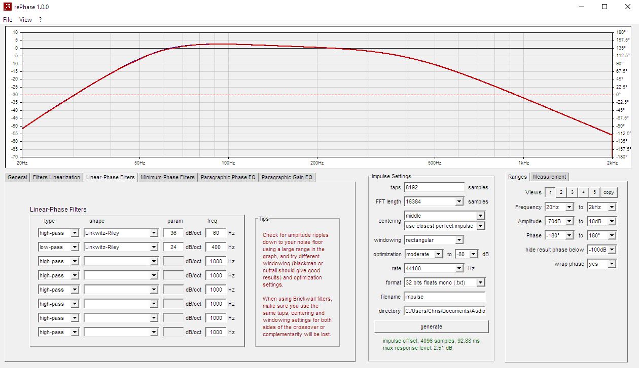
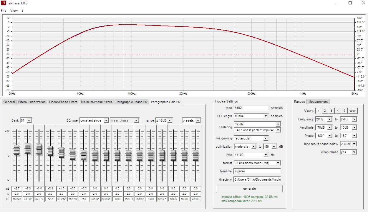
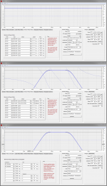
Can think about one half cheating way via windows to get a target curve in Rephase. In example below have set slopes for your midrange LR8 300-2200Hz as IRR filter in second plot and if it means anything one can add flat phase to that doing as in third plot but think phase doesn't matter here we just need the amplitude trace to use as target. Now grab that Rephase window with MS Sniper-tool and save as picture, open that picture with a program that show 1:1 resolution and exactly in same position upon that window place real Rephase session where your correct your midrange, and to quality check your slopes in Rephrase slide with mouse over program icons down on MS taskbar to shift focus between the two windows.
Think its hard to explain the logic in previous tips from pos but some of them is in short to temporary use the opposite correction as a quality check to see if slope is correct (frq point and slope topology) either by observing amplitude example go flat or phase goes flat or phase start turn the predicted 90º per order as the textbook will predict and then turn off that temporary quality check filter again before generating IR-wav file, but think without we are sitting face to face it will be complicated hard to explain further. Also a thing to remember is that if a correction filter don't do as predicted then it could be the measurement correction is based upon is not right or it can be acoustic offset between drivers are not corrected right.
Can think about one half cheating way via windows to get a target curve in Rephase. In example below have set slopes for your midrange LR8 300-2200Hz as IRR filter in second plot and if it means anything one can add flat phase to that doing as in third plot but think phase doesn't matter here we just need the amplitude trace to use as target. Now grab that Rephase window with MS Sniper-tool and save as picture, open that picture with a program that show 1:1 resolution and exactly in same position upon that window place real Rephase session where your correct your midrange, and to quality check your slopes in Rephrase slide with mouse over program icons down on MS taskbar to shift focus between the two windows.
Attachments
Last edited:
Thanks BYRTT, As usual u have posted some neat and clear hacks. Much appreciated.
I was indeed trying see if there was a way to overlay a transparent curve over the rephase window.
Anyway i think i do understand the options posted earlier by Pos, just wanted state that a ref curve was much straightforward and also wanted to check my understanding of the process
I was indeed trying see if there was a way to overlay a transparent curve over the rephase window.
Anyway i think i do understand the options posted earlier by Pos, just wanted state that a ref curve was much straightforward and also wanted to check my understanding of the process
Sorry for the delay!
Crossover are a different thing, because the summed response cannot be minimum-phase with minimum-phase filters.
In any case minimum-phase EQ is a safer bet IMHO.
This can be done in rephase by simply "merging" the different correction.
For example if you have a separate correction for each driver, and then a global correction for room mode, house curves and the like, you simply have to report these correction into each separate driver correction.
Yes, as long as it is good quality IIR (enough precision not to worry about quantization noise) you are good to go with plain ol' IIR for EQ.I'm still getting my head around what I should do with linear phase and what should be minimum phase.
I know linear phase is good for my actual crossovers.
But correcting driver response should be minimum phase so I think it would actually be just fine to do with IIR PEQ, which is much easier to tweak.
I do use minimum-phase for these, but it probably does not matter that much.I think the response curve I'm applying with a low shelf should be done linear phase since it is pretty similar to crossovers.
Crossover are a different thing, because the summed response cannot be minimum-phase with minimum-phase filters.
Can't help you on this, as I tend to avoid room mode corrections myself.But I'm not so sure about trying to level out peaks caused by room modes. It seems like linear phase EQ is the way to go there though.
In any case minimum-phase EQ is a safer bet IMHO.
You can "mix" several correction into one to avoid adding processing delays.Am I really off base with any of that? If not, how would I go about creating a house curve when I'm using 3 separate .wav files now and could even end up with a file per driver in the end? The low shelf I'm using right now spans half the midbass driver frequency range and all of the sub frequencies. I'm going to experiment with it but any advice would be much appreciated.
This can be done in rephase by simply "merging" the different correction.
For example if you have a separate correction for each driver, and then a global correction for room mode, house curves and the like, you simply have to report these correction into each separate driver correction.
Hi mark100,Hi Pos, new poster to rePhase thread.
First, many thanks for your great program!!
Thank you for your kind words and sorry for the delay.
As long as the result curves follow the (complementary) target ones close enough, and as long you take care of time alignment somewhere, you are good to go regardless of any impulse windowing strategy you might have used to reach that goal.I've read your posts to keep filter topology the same on both sides of x-over.
I don't think I need to be concerned with one side of x-over at 650hz using 6144 taps and the other 2048 taps, but I'm wondering if there are any special steps required other than time alignment. (I can do time alignment with either the mixer or DSP amps).
If the cables are not too long I guess you should be okay.Also, I'm simply using a Y cable to feed the spdif coaxial inputs of the two miniDSP units...any prob there?
I use a video coax splitter myself: Adapter Video Signal Verteiler Aktiv RV 1 2P | eBay
or 8 WAY BNC Coaxial TV CCTV DVR Composite Video 1 TO 8 Ports Switch Splitter BOX | eBay (did not test that one)
Of course you need coax/cinch cables with this type of unit: https://www.thomann.de/gb/the_sssnake_1855_bncchinch.htm
As far as sequence with rePhase... my understanding goes like...
1. use Paragraphic Gain(minimum phase) EQ to first flatten response in the passband
2. then use Minimum-Phase Filters 'compensate', and 'time offset' in measurement to flatten phase, and to continue flattening amplitude.
3. Apply Linear-Phase Filters
Q? #1 and #2 affect each other...I assume you just keep going back and forth?
yes!
Yes you might have to use several "compensate" filters in order to compensate for the actual rolloff of your driver, especially with horns wich are not as simple as say a closed box rolloff to address...Q? I'm trying to get amplitude and phase flat through the passband and beyond, at least to -15db corners. So far I have had to use Paragraphic-Phase EQ in addition, to do this. But I read in post 677 that I should never have to use phase EQ for individual drivers...
Am I giving up too soon, going to Phase Eq?
Do you use mulitple HP and LP compensations or something I'm missing?
Also beware of the measurement itself: gating and noise floor can make things difficult to analyse off band.
That is where several measurements at different distances and with different gating parameters come in handy.
It dependsLast Q?
Regarding 'maximum response level' given under generate....
Does it need to stay below zero?
If you have a floating point unit and will control volume in the digital domain somewhere else down the road then you can go past 0dB, but you have to keep the final volume in mind to avoid clipping.
In fact this is similar to IIR.
Again, thanks for a remarkable program...here's a transfer function from smaart when using 2048 taps for MF...been too windy yet,to measure 6144 tap try. I'm stoked how well your program works!
- Home
- Design & Build
- Software Tools
- rePhase, a loudspeaker phase linearization, EQ and FIR filtering tool