Yes, that's the name of the guy who sent me the data. I don't know the history of who's speaker it is or who took the data.
I want to show the rear, but the cardiod nature gives me some trouble with the fitting routines since it assume a monopole at very low frequencies. I can fix that, but as all things it takes time. I bet everyone thought that I'd never get arround to do this much. (It was a nightmare - the code became unstable because of my "hack" programming and I had to go back several versions to get to something from which to rebuild the design.)
I want to show the rear, but the cardiod nature gives me some trouble with the fitting routines since it assume a monopole at very low frequencies. I can fix that, but as all things it takes time. I bet everyone thought that I'd never get arround to do this much. (It was a nightmare - the code became unstable because of my "hack" programming and I had to go back several versions to get to something from which to rebuild the design.)
Yes, that's the name of the guy who sent me the data. I don't know the history of who's speaker it is or who took the data.
I want to show the rear, but the cardiod nature gives me some trouble with the fitting routines since it assume a monopole at very low frequencies. I can fix that, but as all things it takes time. I bet everyone thought that I'd never get arround to do this much. (It was a nightmare - the code became unstable because of my "hack" programming and I had to go back several versions to get to something from which to rebuild the design.)
Do you have different code for each set of measurements? I do not get the calculation errors if I look at the Mensink data, but I still do get them when I open for example the piston cap (unless I change my "Regional settings" off course)...
Attachments

Yes, actually those data sets were done on different programs. Try the Abbey, it was redone on the new program as well. The polar cap was generated in MathCAD. If that works let me know and maybe I can track it down.
Is it the speaker listed as "Mensink"?
Yes, that's the name of the guy who sent me the data. I don't know the history of who's speaker it is or who took the data.
Hi Earl,
It's been a couple months, but the guy who sent you the data is me 😉, see http://www.diyaudio.com/forums/multi-way/192737-2-way-waveguide-cardioid-like-6.html#post2673343
Your program is difficult to get to work at all, but once you do it serves as a great tool! Thanks for uploading the data. I'd like to see that data of the rear response, but I understand it will take you some time. Speaking of which, you've set a precedence 😀 .
Yes, actually those data sets were done on different programs. Try the Abbey, it was redone on the new program as well. The polar cap was generated in MathCAD. If that works let me know and maybe I can track it down.
You are correct, Abbey works ok also now.
keyser, have you considered running the woofer in dipole and then absorbing the rear wave with a wide, thick shield of fiberglass (glass wool)? Of course this shield would need to be offset so as to allow proper dipole execution but if it was wide enough and thick enough you would be able to suppress a large amount of the rearward energy going into the room.
I have no idea why I said this since this is exactly what you did.keyser, have you considered running the woofer in dipole and then absorbing the rear wave with a wide, thick shield of fiberglass (glass wool)? Of course this shield would need to be offset so as to allow proper dipole execution but if it was wide enough and thick enough you would be able to suppress a large amount of the rearward energy going into the room.
Cardioid response.Did anybody ask why the side walls were perforated instead of solid?
nice thread.
I really don't like the first inch of that waveguide.
You can see it on the closeup on the parts-express site.
Then again, $14 ain't bad either, and it seems to measure decent also.
See post #54 (Selenium D220Ti compression driver on the dayton horn)
not a build thread, but... - Page 3
and another graph 3/4 the way down of the dayton.
Audio Asylum Thread Printer
Norman

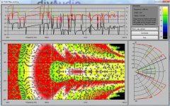
I've been messing with SAW lenses, like used in the Beolab, and have found that they're response shape is cardioid-like. If you look at the speakers, they're a bit similar to an H frame; some of the energy radiates forward, and a fraction of the energy radiates to the back. Here's a measurement of one that I built, unequalized. Yellow is on axis, orange is 22.5 degrees off axis, red is 45 degrees off axis. Grey is 180 degrees off axis, and you'll notice that the output at the rear is down by about ten decibels, and the response shape mirrors the front nicely:

Some more thoughts on "cardiod".
To be a cardiod there must be a mixture of a monopole and a dipole. Since the dipole efficiency is far lower than the monopole, there is always going to be an efficiency loss whenever one creates a cardiod passively. If, like me, one uses a passive crossover, then you are stuck because you can't get a flat response (without serious degradation of the entire systems efficiency). This is a very high price to pay to for a questionable benefit.
Actively you can get exactly what is desired, especially if you use a second driver on the back - remember that this driver need not be of a very high quality since it only affects the directivity and hardly radiates any signal into the direct field. Hence a smaller lower cost driver on the back driven with DSP on both the front and rear drivers and one can achieve a very precise cardiod with both a flat axial response and a flat power response.
If I do go cardiod, thats basically the way that I would do it.
(This entire concept is actually discussed in my transducer book.)
This echoes what I am finding out the hard way.*
I am getting an impressive directivity pattern, with ten decibels of rejection to the back, but it seems like the dipole driver should have more efficiency *and* more displacement than the monopole. IE, in my array I went with a dipole driver that had higher displacement, because I knew that it wouldn't have the 'spring' of a sealed box to put a 'brake' on excursion. And my high excursion driver had low efficiency, as they often do. Now the sound of the combined array is dominated by the monopole response. Basically the polar pattern of the cardioid is almost identical to the polar pattern of the monopole over about half of the bandwidth. Luckily, it's working where it counts, at low frequency.
If I had to do it all over again, I would probably pair dissimilar drivers. Like a 5" monopole and a 10" dipole, or an MTM sandwich with the 5" monopole in the center flanked by 8" dipoles.
* build thread is 'edge of no control'
I wish.
The problem with using a u-frame is that the results aren't predictable. I was shocked to find that the stuffing needs to match from side to side, and even the *consistency* of the stuffing changes the frequency response, the excursion, the distortion, the impedance curve, EVERYTHING.
IE, I learned why John K doesn't use U-Frames even though he wrote the software for them, and why Geddes uses reticulated foam instead of something else (re:consistency.)
just wondering if you have used high density fiberglass like the 700 series by Owens Corning? To obtain even flow through resistance the panel must be on edge to the speaker air flow. Since the panels are compressed the surfaces are denser than the centre of the pane. You might even be able to use it to create some lens action just not sure how much control you would achieve, like JBL did see link. I can say that when used internally for damping the material orientation has a significant impact upon damping. Best regards Moray James.l
http://insulation.owenscorning.ca/assets/0/188/1af6c138-5b49-49c7-8b6b-c39ee0f4159e.pdf
http://www.jblpro.com/pub/obsolete/Acoustic_Lens_Family1.pdf
Last edited:
The resistance enclosure works very well, but it requires a lot of experimentation with locations of the openings and damping material to get optimal results. The heavier, thicker fibreglass panels tend to work well, although it might pose a health hazard. This thread describes my first experiment with a resistance enclosure. Much better results are possible than shown here. A box with openings to the side but none in the back works well even when placed very close to the wall behind it.
A damped U-frame works better at lower frequencies, but as has been said above the exact amount and kind of damping material have a great effect on how well it will work. It requires some room behind the box to work well.
A cardioid composed of a combination of a dipole and a monopole should work fine. You have to equalize both to the same response, because otherwise their phase-relationship will not be the same. I think it should be possible to place this configuration quite close to the wall behind it, because the cancelling sources are in the same vertical plane and cancellation starts right there at the sources - not at some distance behind it, as is the case with a U-frame and a cardioid that consists of two monopoles.
A configuration with two monopoles in line can work very well too. You place one sub behind the other, you invert the phase of the rear sub and add a delay that corresponds with the propagation delay of the sound over that distance. This should work well up to about the frequency where the distance between the subs is about a quarter wavelength.
Last year I started a speaker company with two other guys and our speakers incorporate the resistance-box principle. We have been working hard developing our products and now they're almost finished. The website will go live soon. Here you'll find a prelaunch landing page:
Synergy Acoustics
Exciting news Keyser! I will follow your new start-up with big interest.
Why is it that a resistance enclosure with closed back and open sides works better mounted close to the wall? Is it a measurable effect or something you experienced by listening to different types of cardoids?
I'm experimenting with this myself on a 12" midbass much like what you used in this thread. The rear of the speaker will be about 40cm to the rear wall. It will be used from 200hz and up only. Do you think it should be open on the back or closed?
Thanks, Frederik!
I meant to say that the sound of a cardioid resistance enclosure is affected less by a close front-wall, not that the wall improves the sound. Measurements have shown that the wall hardly affects the response. We tested this by measuring outside, letting the speaker face up at varying distances to the ground. The distance between the speaker and the ground hardly affected the frequency resposnse, even if the speaker practically lay back-down on the ground. I think the reason why this kind of enclosure works well near the wall is that the cancellation is realized in close proximity to the source. Whether you measure at half a meter or at two meters, you measure practically the same directivity.
Based on my experience, I'd say holes in only the sides will probably work best for your application, but I'd advise you to experiment with it.
- Status
- Not open for further replies.
- Home
- Loudspeakers
- Multi-Way
- 2-way: Waveguide + Cardioid-like