Here is what I think I would do next fwiiw.
(Before starting something like this I would print out the schematic, measure all the existing actual voltages and write them on it)
- unsolder the wire to the screens (pins 6) from the junction of R12 & R13. (Personally I would just cut 5mm in to give me an easier soldering point)
- I would then solder in a 10k 1w resistor from the junction to the screen wire
- then measure screen voltage. If voltage 300 or less go to next step, if not, replace 10k with something bigger.
- next jumper/short out the 470R cathode resistor - reducing the total cathode resistance from 1110R to 640R
- measure all the voltages again (anode, screen, cathode, both ends of R12)
- calculate anode and screen dissipation
If all good unshort the 470R and short the 640R. Repeat the 2 steps above.
Take it slowly, take good readings, think about what the results mean.
The goal is to eventually get as close to the stock value of 220R as possible without melting your amp (or yourself) and learning as you go.
Ok, got the voltage down to 307v using a 33k resistor
With the 680ohm cathode bias resistor these were the bias calculater numbers:
Tube Max Design Dissipation =
12watts 100% Pa
Class AB Fixed Bias 50% Cool =
22.7
DC milliamps 60% Average =
27.3
70% Max Safe Dissipation =
31.8
Cathode Bias 85% Cool =
38.6
DC milliamps 95% Average =
43.2
100 % Max Safe Dissipation =
45.5
Tube Dissipation Using Cathode Resistor Voltage Drop
You must enter Tube Type and Plate-to-Cathode Voltage above before calculating Tube Dissipation.
Enter Number of Tubes that share a cathode resistor:
2
Enter Voltage Across Cathode Resistor:
25.4
DC volts Voltage drop across the cathode resistor.
Enter Cathode Resistor:
680
ohms Cathode resistor ohm value.
Calculate
Total Cathode Current =
37.4
DC milliamps = Voltage Across Cathode Resistor / Cathode Resistor.
Total Plate Current =
35.3
DC milliamps = Cathode Current minus approximate screen current of 5.5%.
Plate Current per Tube =
17.7
DC milliamps = Total Plate Current / Number of Tubes.
Plate Dissipation per Tube =
4.7
watts = Plate Current per Tube x Plate Voltage.
Plate Dissipation per Tube % =
39.2
% Plate Dissipation per Tube % = Plate Dissipation per Tube / Tube Max Rated Dissipation.
If your tube is a triode then there is no screen current so your plate current is
18.7
milliamps, your plate dissipation is
4.9
watts and
40.8
%.
Tube Dissipation Using Plate Current
Use this calculator when you measure the actual plate current. You must enter Tube Type and Plate-to-Cathode Voltage above before calculating Tube Dissipation.
Enter Plate Current:
35.3
DC milliamps
Calculate
Plate Dissipation =
9.3
watts = Plate Voltage * Plate Current.
Plate Dissipation % =
77.7
% = Plate Dissipation / Tube Maximum Rated Dissipation.
With the 470 ohm resistor these were the numbers: Not real sure what this all means so I'll leave it to the experts [and do some reading on the topic]
But this looks too high, so what bias resistor value would be ideal?
Tube Max Design Dissipation =
12
watts 100% Pa
Class A Fixed Bias 70% Cool =
25.5
DC milliamps 80% Average =
29.1
90% Max Safe Dissipation =
32.7
Class AB Fixed Bias 50% Cool =
18.2
DC milliamps 60% Average =
21.8
70% Max Safe Dissipation =
25.5
Cathode Bias 85% Cool =
30.9
DC milliamps 95% Average =
34.5
100 % Max Safe Dissipation =
36.4
Tube Dissipation Using Cathode Resistor Voltage Drop
You must enter Tube Type and Plate-to-Cathode Voltage above before calculating Tube Dissipation.
Enter Number of Tubes that share a cathode resistor:
2
Enter Voltage Across Cathode Resistor:
22.3
DC volts Voltage drop across the cathode resistor.
Enter Cathode Resistor:
470
ohms Cathode resistor ohm value.
Calculate
Total Cathode Current =
47.4
DC milliamps = Voltage Across Cathode Resistor / Cathode Resistor.
Total Plate Current =
44.8
DC milliamps = Cathode Current minus approximate screen current of 5.5%.
Plate Current per Tube =
22.4
DC milliamps = Total Plate Current / Number of Tubes.
Plate Dissipation per Tube =
7.4
watts = Plate Current per Tube x Plate Voltage.
Plate Dissipation per Tube % =
61.7
% Plate Dissipation per Tube % = Plate Dissipation per Tube / Tube Max Rated Dissipation.
If your tube is a triode then there is no screen current so your plate current is
23.7
milliamps, your plate dissipation is
7.8
watts and
65
%.
Tube Dissipation Using Plate Current
Use this calculator when you measure the actual plate current. You must enter Tube Type and Plate-to-Cathode Voltage above before calculating Tube Dissipation.
Enter Plate Current:
44.8
DC milliamps
Calculate
Plate Dissipation =
14.8
watts = Plate Voltage * Plate Current.
Plate Dissipation % =
123.2
% = Plate Dissipation / Tube Maximum Rated Dissipation.
Last edited:
That's great progress.
Are you learning using the online calculators?
The reason I suggested measuring voltages/currents - make a change-re measure the v/I was so you could learn the relationships.
I don't need to see everything on the online calc page, and it doesn't show the voltages you have measured.
Are you learning using the online calculators?
The reason I suggested measuring voltages/currents - make a change-re measure the v/I was so you could learn the relationships.
I don't need to see everything on the online calc page, and it doesn't show the voltages you have measured.
So 65% Pd is looking good. Dropping the screen voltage will let you reduce cathode R some more if you wish.
But you still haven't told me how the plate voltages move with each change.
The trend is as important as the absolute values because it will show how the replacement transformer behaves under different loads.
But you still haven't told me how the plate voltages move with each change.
The trend is as important as the absolute values because it will show how the replacement transformer behaves under different loads.
Well, I'm still trying to wrap my head around all this. 
But I am measuring the voltage with each change and observing the differences.
Priority #1 right now is to get the amp in gig condition as if all goes well I'll give it a go saturday!
Do you think the 270v on the screens is a good voltage?
And any suggestions for a bias resistor or is it basically whatever sounds best to me? With the 470ohm it seemed to break up above 5 on the volume. That would be ideal for some uses but I'm wanting loud,clean headroom. [well, as much as possible from a 12w amp!]
I feel the noise level is going to be the big problem as it was still pretty buzzy with the new F&T 22uf caps. I changed the 25uf,10uf and 2uf as well.
But I am measuring the voltage with each change and observing the differences.
Priority #1 right now is to get the amp in gig condition as if all goes well I'll give it a go saturday!
Do you think the 270v on the screens is a good voltage?
And any suggestions for a bias resistor or is it basically whatever sounds best to me? With the 470ohm it seemed to break up above 5 on the volume. That would be ideal for some uses but I'm wanting loud,clean headroom. [well, as much as possible from a 12w amp!]
I feel the noise level is going to be the big problem as it was still pretty buzzy with the new F&T 22uf caps.
I changed the 25uf,10uf and 2uf as well.So 65% Pd is looking good. Dropping the screen voltage will let you reduce cathode R some more if you wish.
But you still haven't told me how the plate voltages move with each change.
The trend is as important as the absolute values because it will show how the replacement transformer behaves under different loads.
The plate to cathode voltage has stayed right around 330v, regardless of the bias resistor changes
I think 270v on screens is OK considering original schematic figure of 287v.
You could probably drop the bias resistor down a bit more - your bias calculator implies 30mA thro your cathode resistor is still cool.
Might give you some more clean headroom but not enough to hear I reckon.
If you want louder you need bigger/more sensitive speakers.
Hum may be from too much ripple from the PSU but more likely dodgy grounding - do some homework.
I am offline for a week or so now - maybe someone else will pick up the baton.
Cheers, and happy DIY
JimG
Ok, got the 50 uf P/S caps in and it made a noticable difference. It still has a pretty good hum though. I could gig with it as is but recording would be out. The grounds all appear to be very solid, so I think its related to the PT. What is ''power supply ripple'' and what can be done to minumize it?
If anybody has any suggestions for lowering power supply noise I would be gratetfull!
[The amp sounds outstanding by the way, and it has a JBL D120F in it. Probably the loudest and heaviest 12w amp on the planet]
If anybody has any suggestions for lowering power supply noise I would be gratetfull!
[The amp sounds outstanding by the way, and it has a JBL D120F in it. Probably the loudest and heaviest 12w amp on the planet]
Attachments
One strange thing is the pilot light stays on dimly when the amp is turned off. And theres a 1m resistor splice in line from the pilot light to the switch.?Thats not on the schematic.
I just gave the amp a good listen and the buzz is still too loud.It would drive our sound man crazy.
Its from the power suplly cause vol/tone control adjustments dont affect it.
I just gave the amp a good listen and the buzz is still too loud.It would drive our sound man crazy.
Its from the power suplly cause vol/tone control adjustments dont affect it.
Not sure about the resistor in series with the pilot light - maybe a way to use a low voltage pilot on the full mains voltage - but 1M seems very high? I would leave it alone for now.
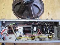
The layout diagram in post #48 indicates that there should be a ground connection on the vol. pot - on the terminal where a wire links across to a terminal on the tone pot. Where does that ground connection go to, and is it making a good solid connection.
Also the grounding scheme seems to rely on the input jacks making good mechanical contact with the chassis - might be worth unscrewing the jacks and cleaning the chassis and the jacks (where they touch) with some emery cloth.
A minor thing - but it might just help. I think your new 50+50 cap has two green wires and one black wire coming out. Try bending both the green wires over to the other side so that they are close to the black wire.
The current in these wires is very 'buzzy' and by minimising the 'loop area' we can minimise the amount of interference radiated out from this circuit.
The current in these wires is very 'buzzy' and by minimising the 'loop area' we can minimise the amount of interference radiated out from this circuit.
Another thing - comparing the photos in posts #89 and #110, it looks like you have moved the black wire coming from the PT to a different connection point. It should be on the connection point where the cathode resistor connects to the 50+50 cap, not where the 25uF cathode bypass cap connects.
I know it looks like an insignificant change, but the current out of that 50+50 cap back into the transformer is part of the loop with the biggest buzz current in the whole amp. Even the very low resistance of that short section of ground wire, which now 'shares' that buzz current with the current coming out of the cathode resistor, could be significant.
Definitely worth a try to put that wire back to where it was.
Last edited:
Thanks Malcom, will do! Yeah, 1 meg seems high for a current limiting resistor? And there is no resistor in the schematic?
There are 2 ground connections in my amp. The volume/tone pots which ground all the board connections and the heater wire ground by the preamp tube. Of course the power plug is grounded to the chassis as well.
I think what I'm hearing is that power supply ripple. This power supply seems to 'vibrate' physically a bit more than most, and the buzz seems to be linked to it. The tone pot when maxed adds a bit of hiss but nothing out of the ordinary. But as soon as this amp is plugged in and turned on even with the vol/tone down the power supply noise is there, and it is very noticable.My wife said ''what is that noise'' so I know our soundman isnt going to like it.
Another thing - comparing the photos in posts #89 and #110, it looks like you have moved the black wire coming from the PT to a different connection point. It should be on the connection point where the cathode resistor connects to the 50+50 cap, not where the 25uF cathode bypass cap connects to ground.
I know it looks like an insignificant change, but the current out of that 50+50 cap back into the transformer is part of the loop with the biggest buzz current in the whole amp. Even the very low resistance of that short section of ground wire, which now 'shares' that buzz current with the current coming out of the cathode resistor, could be significant.
Definitely worth a try to put that wire back to where it was.
Malcom, good looking out! You are absolutely correct! I'll pull the chassis tomarrow and check that out.
Thanks 4 the assist!!
Last edited:
Not sure about the resistor in series with the pilot light - maybe a way to use a low voltage pilot on the full mains voltage - but 1M seems very high? I would leave it alone for now.
The layout diagram in post #48 indicates that there should be a ground connection on the vol. pot - on the terminal where a wire links across to a terminal on the tone pot. Where does that ground connection go to, and is it making a good solid connection.
Also the grounding scheme seems to rely on the input jacks making good mechanical contact with the chassis - might be worth unscrewing the jacks and cleaning the chassis and the jacks (where they touch) with some emery cloth.
I put really toothy washers on the input jacks and cranked em' down, but I will give cleaning the chassis a go as well. I'll check the vol connection as well when I pul the chassis. I was contemplating running a wire from the input jack to the heater wire ground. Would that be worth a try or not necassary?
Last edited:
... I was contemplating running a wire from the input jack to the heater wire ground. Would that be worth a try or not necassary?
Not necessary if the jacks are making a good ground - and in fact it would create a small 'ground loop' which could make things worse.
The old way of grounding the jacks and the pots to the chassis is not really the modern way to do it, but it should work well enough. So let's see if the suggestions I've made have any effect first.
After that we could try a more modern approach with insulated jacks and dedicated ground connections rather than 'through the chassis', but that would start to get a bit drastic.
At the same time, I'm not very familiar with phase inverter transformers. As magnetic components they are capable of picking up hum and buzz from stray magnetic fields (e.g. from the PT) - let's hope that is not the problem we are facing.
Great, I have a feeling that wire in the wrong location might be an issue. Glad you spotted that!.
I've owned one of these in the past [6v6 model] and it was pretty quiet,and others have said its a great recording amp.I will say I'm on a MISSION now, cause this amp sounds killer and is LOUD and clean! Honestly, its a little 12w twin reverb [without the reverb of course]
I dont think the phase inverter is the problem
 unless mine is dodgey.
Last edited:
- Status
- This old topic is closed. If you want to reopen this topic, contact a moderator using the "Report Post" button.
- Home
- Live Sound
- Instruments and Amps
- questions about Fender Musicmaster Bass amp schematic