The last line in my post 71 meant "don't attach to chassis". Sorry I didn't make this clearer.
PS. Malcolm knows more than me 🙂
PS. Malcolm knows more than me 🙂
Last edited:
I wouldn't put the 'centre tap' resistors near a sensitive preamp tube, as they might induce hum.
On the 6AQ5 should be OK, but run a ground wire from there back to your preamp signal ground point.
Maybe I shouldnt be messing with this as I dont know where the preamp signal ground point is. I can change the filter caps so I'll see if they kill the noise.
I really want it back to 100% stock but apparantly I cant use the 220ohm bias resistor if the guy used a 1k in its place.
I would try the 1k 10watt resistor to lower the screen voltage but that junction where the diodes meet is already pretty full with filter cap,resistor,2 diodes and an OT lead so I'm not sure I can stuff a 10w resistor lead in there as well.
I guess what puzzles me is if this PT was supposed to be a direct 1-1 replacement why dont the stock component values work?
😕
I wouldn't put the 'centre tap' resistors near a sensitive preamp tube, as they might induce hum.
On the 6AQ5 should be OK, but run a ground wire from there back to your preamp signal ground point.
The peamp tube pins 4 & 5 are grounded to the chassis, is that what you mean?
I think your preamp tube is a 12ax7 ? (Sorry, it's a long thread!) In which case pins 4 and 5 are for the heater.
You should only ground one point in the whole heater string and that point should be the junction point of the two 100 ohm resistors. The questions is then where to ground it.
My first suggestion was to attach the two resistors somewhere near the PT, but the 6AQ5 heater pins will do. Now we need to ground the junction point of those two resistors. Conventional practice is to run a wire from that junction to a signal ground near the first pre-amp tube.
Best practice is usually to only have two connections to the chassis - a signal ground point and a safety ground point.
I think your preamp tube is a 12ax7 ? (Sorry, it's a long thread!) In which case pins 4 and 5 are for the heater.
You should only ground one point in the whole heater string and that point should be the junction point of the two 100 ohm resistors. The questions is then where to ground it.
My first suggestion was to attach the two resistors somewhere near the PT, but the 6AQ5 heater pins will do. Now we need to ground the junction point of those two resistors. Conventional practice is to run a wire from that junction to a signal ground near the first pre-amp tube.
Best practice is usually to only have two connections to the chassis - a signal ground point and a safety ground point.
Yes, its a 12AX7.
Ok, I'll run a wire over to the signal ground point.
Done!
Last edited:
I guess what puzzles me is if this PT was supposed to be a direct 1-1 replacement why dont the stock component values work?
😕
The new transformer is designed to provide the stock voltage at a current draw of 170mA.
Your amp is currently drawing under 40mA (no signal). So voltage will be higher.
We need to solve 1 problem at a time.
I suggest we Leave the hum for now and focus on voltages and biasing.
Your call.
The new transformer is designed to provide the stock voltage at a current draw of 170mA.
Your amp is currently drawing under 40mA (no signal). So voltage will be higher.
We need to solve 1 problem at a time.
I suggest we Leave the hum for now and focus on voltages and biasing.
Your call.
Thats good with me! I think the 40 year old filter cap replacement will do wonders for the hum [fingers crossed]
Before I take the journey to the electronics shop I'd like to get a parts list together.I was going to just get afew values of 10watt resistors: 1k/1k7/2k but I'll wait for advice on this
The new transformer is designed to provide the stock voltage at a current draw of 170mA.
Your amp is currently drawing under 40mA (no signal). So voltage will be higher.
Oh oh, does that mean I could run 6L6's in this thing with new sockets?
I know I said I just wanted a stock MMB amp but....

Wait, I'm getting way ahead of myself again..
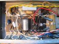
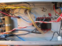
A couple photos for reference if that helps:
And the 6AQ5's will be fine...
And the 6AQ5's will be fine...
Attachments
Last edited:
Can you confirm what pins 4, 5 and 9 of the 12ax7 are connected to? It's hard to see for sure in the photo, but it looks strange to me.
Can you confirm what pins 4, 5 and 9 of the 12ax7 are connected to? It's hard to see for sure in the photo, but it looks strange to me.
4&5 heater wire to chassis ground, 9 heater wire. Maybe you are seeing the small socket on the right as the 12ax7, its actually the first 6AQ5.the socket was replaced by a previous owner.
Last edited:
Pins 4 and 5 should be connected together and to one heater wire (but not to ground). The other heater wire should connect to pin 9.
It won't work properly if you ground the artificial centre tap and ground anywhere else in that heater circuit at the same time.
(I'm looking at the socket at the extreme left.)
It won't work properly if you ground the artificial centre tap and ground anywhere else in that heater circuit at the same time.
(I'm looking at the socket at the extreme left.)
Last edited:
Pins 4 and 5 should be connected together and to one heater wire (but not to ground). The other heater wire should connect to pin 9.
It won't work properly if you ground the artificial centre tap and ground anywhere else in that heater circuit at the same time.
(I'm looking at the socket at the extreme left.)
But Fender wired it that way, one heater wire goes to pin 4, threads through pin 5 and goes to chassis ground.
So I should un-do the Fender ground scheme? Its a much more robust ground than my 1/4watt resistors and long run of thin wire?
Last edited:
But Fender wired it that way, one heater wire goes to pin 4, threads through pin 5 and goes to chassis ground.
So I should un-do the Fender ground scheme? Its a much more robust ground than my 1/4watt resistors and long run of thin wire?
You can choose either way. If you go for the 'stock' Fender option you need to remove the artificial centre tap resistors altogether.
Or, you can keep the artificial centre tap and remove the ground on pin 5. This (more modern) way will give you less hum. The 'robustness' of this ground is not really an issue since there is only a tiny current going into ground.
In the early days amps were low gain and were not usually played at max. volume. I expect the early players liked to hear their amp humming a bit, as long as it wasn't loud enough to reach the audience, so they knew it was working!🙂
Outstanding! Re-did the center taps with 1/2 watt resistors [and a bit thicker wire] and grounded them where the preamp pins 4/5 were grounded. Removed that connection to ground.
Noticable buzz reduction! Still a good amount, but much better.
Noticable buzz reduction! Still a good amount, but much better.
The new transformer is designed to provide the stock voltage at a current draw of 170mA.
Your amp is currently drawing under 40mA (no signal). So voltage will be higher.
We need to solve 1 problem at a time.
I suggest we Leave the hum for now and focus on voltages and biasing.
Your call.
Ready whenever you are free!

You are correct, the voltage should be around 250v so its way high, and the bias is cold.
got this from the 'my bias calculator' with the help of another forum member. https://robrobinette.com/Tube_Bias_Calculator.htm
1150 ohms cathode resistance
323v plate-to-cathode
33.8v drop across the cathode resistor
Per Tube Dissipation
13.9 milliamps
4.5 watts with a max rating of 12 watts
38% of max dissipation
Attachments
Last edited:
Heres all the numbers for my amp, not sure what they mean or where to go from here.These are for a 12w 6v6 however.I think I'm ok with the bias being on the cool side,but the voltage needs to be lower!
6V6 Tube Max Design Dissipation =
12
watts 100% Pa
Class A Fixed Bias 70% Cool =
26
DC milliamps 80% Average =
29.7
90% Max Safe Dissipation =
33.4
Class AB Fixed Bias 50% Cool =
18.6
DC milliamps 60% Average =
22.3
70% Max Safe Dissipation =
26
Cathode Bias 85% Cool =
31.6
DC milliamps 95% Average =
35.3
100 % Max Safe Dissipation =
37.2
Tube Dissipation Using Cathode Resistor Voltage Drop
You must enter Tube Type and Plate-to-Cathode Voltage above before calculating Tube Dissipation.
Enter Number of Tubes that share a cathode resistor:
2
Enter Voltage Across Cathode Resistor:
32.8
DC volts Voltage drop across the cathode resistor.
Enter Cathode Resistor:
1000
ohms Cathode resistor ohm value.
Calculate
Total Cathode Current =
32.8
DC milliamps = Voltage Across Cathode Resistor / Cathode Resistor.
Total Plate Current =
31
DC milliamps = Cathode Current minus approximate screen current of 5.5%.
Plate Current per Tube =
15.5
DC milliamps = Total Plate Current / Number of Tubes.
Plate Dissipation per Tube =
5
watts = Plate Current per Tube x Plate Voltage.
Plate Dissipation per Tube % =
41.7
% Plate Dissipation per Tube % = Plate Dissipation per Tube / Tube Max Rated Dissipation.
If your tube is a triode then there is no screen current so your plate current is
16.4
milliamps, your plate dissipation is
5.3
watts and
44.2
%.
Tube Dissipation Using Plate Current
Use this calculator when you measure the actual plate current. You must enter Tube Type and Plate-to-Cathode Voltage above before calculating Tube Dissipation.
Enter Plate Current:
31
DC milliamps
Calculate
Plate Dissipation =
10
watts = Plate Voltage * Plate Current.
Plate Dissipation % =
83.4
% = Plate Dissipation / Tube Maximum Rated Dissipation.
Last edited:
- Status
- Not open for further replies.
- Home
- Live Sound
- Instruments and Amps
- questions about Fender Musicmaster Bass amp schematic