All good news 🙂
What are the new dissipation figures for the plates and screens?
These figures are for the 6v6GT tube, close enough I guess..
plate dissipation per tube- 6.2 watts @ 51.7%
plate dissipation total 12.4 watts @ 103.5%
The amp is running so much cooler [temperature] with the PT fixed and its quiet as can be. I may put all the carbon comp resistors back in as they werent really the noise problem at all.
Last edited:
I'm exceeding the max dissipation, does that look ok to you?
Not certain how hard I'm pushing the 6AQ5's..
Not certain how hard I'm pushing the 6AQ5's..
You appear to still be using the online calculator (and using voltage figures off the schematics?).
I think you would learn/understand more if you measured the voltages (plate, screen, cathode) in your own amp every time you make a change, calculate currents using ohm's law, then calculate plate and screen dissipation figures with watts= volts x current.
At the voltages you are telling us the risk may be in the screens dying long before the plates turn red.
What lessens the risk is your preference for playing clean. As soon as the tubes start clipping your screen current will go up rapidly.
From what I read on this forum the addition of 1-2k screen stoppers to your output tubes will again reduce risk of screen failure.
Cheers.
Keep learning.
JimG
You appear to still be using the online calculator (and using voltage figures off the schematics?).
I think you would learn/understand more if you measured the voltages (plate, screen, cathode) in your own amp every time you make a change, calculate currents using ohm's law, then calculate plate and screen dissipation figures with watts= volts x current.
At the voltages you are telling us the risk may be in the screens dying long before the plates turn red.
What lessens the risk is your preference for playing clean. As soon as the tubes start clipping your screen current will go up rapidly.
From what I read on this forum the addition of 1-2k screen stoppers to your output tubes will again reduce risk of screen failure.
Cheers.
Keep learning.
JimG
Do the grid stoppers hang over each output tube? Where would I attach them?
I did measure the voltages with each change,but used the online calculator instead of ohms law.
The voltages after the last change were as follows
cathode to ground = 30.4v
cathode to plate = 328v
screen = 354v
If you see a problem or suggest I go back to a voltage limiter resistor to bring down the voltage let me know!
Do the grid stoppers hang over each output tube? Where would I attach them?
...
Screen stoppers would be soldered to 'grid 2' or 'screen grid' (pin 6 on a 6AQ5) of each output tube.
Not sure, but at present there is probably a wire coming from the 1k 'screen dropper' in the power supply to one of the pin 6s and a further wire 'daisy chaining' across to the other pin 6.
You need the wire from the 1k 'screen dropper' coming to a junction which splits into two to supply the two new screen stopper resistors.
Last edited:
Screen stoppers would be soldered to 'grid 2' or 'screen grid' (pin 6 on a 6AQ5) of each output tube.
Not sure, but at present there is probably a wire coming from the 1k 'screen dropper' in the power supply to one of the pin 6s and a further wire 'daisy chaining' across to the other pin 6.
You need the wire from the 1k 'screen dropper' coming to a junction which splits into two to supply the two new screen stopper resistors.
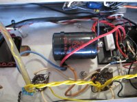
I think I understand. Instead of 1 wire [voltage drop resistor in my photo] going to the screen of 1 power tube, you replace that with 2 1k resistors and run one to the screen of each 6AQ5? I 'think' I understand could buy me a one way ticket to chernobyl...
Attachments
Last edited:
I think I understand. Instead of 1 wire [voltage drop resistor in my photo] going to the screen of 1 power tube, you replace that with 2 1k resistors and run one to the screen of each 6AQ5? I 'think' I understand could buy me a one way ticket to chernobyl...
Sorry, I think I was forgetting you already had that extra 'voltage drop resistor' in your circuit. I think that is already doing the job for you.
What is the ohms value and watts value of that 'voltage drop resistor'?
Last edited:
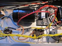
No, currently it is removed. That photo is from a previous state of my amp.
There is now just a wire there and the screen voltage is 354v
I added it on a recommendation here, but decided to try it without it as it wasnt inthe amp when I got it, and my logic was more voltage could improve the clean headroom...if it doesnt toast the tubes!
There is now just a wire there and the screen voltage is 354v
I added it on a recommendation here, but decided to try it without it as it wasnt inthe amp when I got it, and my logic was more voltage could improve the clean headroom...if it doesnt toast the tubes!
I think djgibson51 and I are worried that your screen voltages are back to being too high. Keep in mind that the tube datasheet specifies 250V as the max. screen voltage. The risk is that you may destroy the output tubes through excessive screen dissipation. If it's working OK, you tend to only play clean, and are happy to take some risk, stay as you are. You are correct that the high screen voltage will increase your clean headroom.
Or, to reduce the risk you should put screen stoppers of (let's say) 2k in series with the supply to each screen grid (pin 6).
Or, to reduce the risk you should put screen stoppers of (let's say) 2k in series with the supply to each screen grid (pin 6).
Last edited:
Ok, just to be clear using the photo above, Replace the one screen stopper in the photo with a 2k resistor, the replace the white wire to the other tubes screen with a 2k resistor? Sorry if I'm a bit unclear on the installation, I just want to do it properly. 😱
Last edited:
Ok, just to be clear using the photo above, Replace the one screen stopper in the photo with a 2k resistor, the replace the white wire to the other tubes screen with a 2k resistor? Sorry if I'm a bit unclear on the installetion, I just want to do it properly. 😱
More or less, but you don't want to have 2k going to one tube and then another 2k adding on to that to get to the next tube. You need 2k to each tube from the same source point.
The 2k stoppers will only reduce headroom a tiny bit, but will provide a voltage reduction on the screen when and if it starts to draw a large current (e.g. during clipping).
Ok, got it! So, thats less intrusive than using one resistor of say 33k [307v on the screen in my amp] or 12k [317v on the screen in my amp] ?
I suppose the 2k resistors keep the voltage higher, but come in to play when the amp is taxed or being clipped hard?
And wouldnt one 2k to the first tube be ok? as then the white wire to the other tube would also have the 2k load on it?
Last edited:
Yes, that's it. The screen stoppers are usually there to add some extra safety margin when you already have the screen voltages at datasheet value, but they will give some added protection in your set up.
They also help to stabilise the amp.
They also help to stabilise the amp.
Got it, thanks Malcolm. The amp sounds great with the added voltage so I'll add the screen stopper and see how tube life goes...
Thx yet again! 😎
Thx yet again! 😎
And wouldnt one 2k to the first tube be ok? as then the white wire to the other tube would also have the 2k load on it?
Yes that would be OK. Only one tube clips at a time in a push-pull set up.
You don't get so much 'stability improvement' that way, but I don't think you are having any problem with that.


Excellent.
And now you can
measure the new voltage on your screens (won't have changed significantly),
measure the voltage across a 2k2 screen stopper resistor,
calculate screen current (ohm's law),
And finally calculate screen dissipation (current thro screen stopper times voltage on screen).
And now you can
measure the new voltage on your screens (won't have changed significantly),
measure the voltage across a 2k2 screen stopper resistor,
calculate screen current (ohm's law),
And finally calculate screen dissipation (current thro screen stopper times voltage on screen).
- Status
- Not open for further replies.
- Home
- Live Sound
- Instruments and Amps
- questions about Fender Musicmaster Bass amp schematic