According to this data sheet:
http://www.r-type.org/pdfs/6aq5.pdf
the max. cathode-to-plate voltage (called anode voltage in the sheet) is 250V.
With a lot of tubes you can exceed that limit though.
http://www.r-type.org/pdfs/6aq5.pdf
the max. cathode-to-plate voltage (called anode voltage in the sheet) is 250V.
With a lot of tubes you can exceed that limit though.
Last edited:
Thanks Malcom! I may try a 250ohm and watch the tubes any red plating.
I dont really understand the dissipation and how it relates to biasing an amp. I always heard the ma rating like 20ma per tube,40ma a pair etc.
I'm not expecting you to enlighten me on this as you guys have all been real generous with your time...but if you find yourself with a little extra time I'm all ears.
I thought I would share a revised schematic from a respected amp builder who knows his way around these MMB amps [Winfield Amps].
He drew up a schematic for me with changes to the front end for reducing V1 noise and using fender 'blackface' values on VI.
Interesting stuff!
Attachments
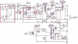
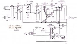
^ That was the stock values , heres the revised schematic...
I'm going to try these values and shield the input wires as well as the long V1 to Vol pot wire. The tone control gets a bit hissy so this might help in that area.
But further mods will have to wait until my pack of 1w metal film resistors arrives from China...
I'm going to try these values and shield the input wires as well as the long V1 to Vol pot wire. The tone control gets a bit hissy so this might help in that area.
But further mods will have to wait until my pack of 1w metal film resistors arrives from China...
Attachments
Last edited:
At the risk of oversimplifying:... dissipation and how it relates to biasing an amp. I always heard the ma rating like 20ma per tube,40ma a pair etc....
Most people prefer the sound of a tube amp when it is 'warm' biased.
To make the bias warmer, the grid-to-cathode voltage needs to be made less negative (or in other words cathode-to-grid voltage made less positive). This will increase the plate current. So for a particular amp, it is conventional to talk about the bias in terms of the amount of plate current.
The limitation on how warm we can make the bias is usually the plate dissipation. This is heat produced in the plate - which can cause 'red plating' if it is too high.
The heat produced in the plate is proportional to the number of electrons hitting the plate over a given time (proportional to plate current) and the average kinetic energy of those electrons (proportional to cathode-to-plate voltage). It turns out the heat going into the plate is just the usual formula of voltage multiplied by current.
At the risk of oversimplifying:
Most people prefer the sound of a tube amp when it is 'warm' biased.
To make the bias warmer, the grid-to-cathode voltage needs to be made less negative (or in other words cathode-to-grid voltage made less positive). This will increase the plate current. So for a particular amp, it is conventional to talk about the bias in terms of the amount of plate current.
The limitation on how warm we can make the bias is usually the plate dissipation. This is heat produced in the plate - which can cause 'red plating' if it is too high.
The heat produced in the plate is proportional to the number of electrons hitting the plate over a given time (proportional to plate current) and the average kinetic energy of those electrons (proportional to cathode-to-plate voltage). It turns out the heat going into the plate is just the usual formula of voltage multiplied by current.
On the bias calculator with my 470ohm resistor the plate dissipation percentage is 119.4%. Shouldnt I try to get that under 100%? With the 680 ohm the plate dissipation percentage is 97.1%. That looks better to me but is it ok to exceed this percentage?
When I put the measured values you gave me into the calculator, it agrees with my calculations (about 7.5 watts and 60% of max.):
https://robrobinette.com/Tube_Bias_Calculator.htm
Tube type = 6V6GT (closest to 6AQ5 from the available list.)
Plate to cathode voltage = 327
Voltage across cathode resistor = 21.8
Cathode resistor = 470
https://robrobinette.com/Tube_Bias_Calculator.htm
Tube type = 6V6GT (closest to 6AQ5 from the available list.)
Plate to cathode voltage = 327
Voltage across cathode resistor = 21.8
Cathode resistor = 470
Last edited:
When I put the measured values you gave me into the calculator, it agrees with my calculations (about 7.5 watts and 60% of max.):
https://robrobinette.com/Tube_Bias_Calculator.htm
Tube type = 6V6GT (closest to 6AQ5 from the available list.)
Plate to cathode voltage = 327
Voltage across cathode resistor = 21.8
Cathode resistor = 470
Yes, I get the same reading in the second step 'Tube Dissipation Using Cathode Resistor Voltage Drop'
But in the 3rd step 'Tube Dissipation Using Plate Current' I get 14.3 watts and dissipation percentage 119%?
Sorry if I'm a bit slow here but which 'step' do you go by?
In that step you have to put the plate current for one tube, rather than the total plate current for the two tubes.... in the 3rd step 'Tube Dissipation Using Plate Current' I get 14.3 watts and dissipation percentage 119% ...
Big success today regarding PT hum. The transformer itself wasn't tightened down very firmly and was vibrating. Tightening the 4 mounting bolts really quieted this thing down.
Second success, removed the 1meg resistor from the pilot light and its nice and bright and when the amp is turned off its also completely off. Cant figure out why that resistor was there at all?
I swapped the 470ohm cathode resistor for a 330ohm and got 9.3 watts and 77.7% dissipation.
Second success, removed the 1meg resistor from the pilot light and its nice and bright and when the amp is turned off its also completely off. Cant figure out why that resistor was there at all?
I swapped the 470ohm cathode resistor for a 330ohm and got 9.3 watts and 77.7% dissipation.
Thanks everybody thats posted! You guys are great!
I've learned alot and the amp sounds great and is very quiet now! I'm shocked that a loose PT can creat such a buzz in a circuit. But relieved that it was an easy fix!
I've learned alot and the amp sounds great and is very quiet now! I'm shocked that a loose PT can creat such a buzz in a circuit. But relieved that it was an easy fix!
Hum? To start with
- Bigger smoothing caps than 20-22u. (There is no magic in the stock specs)
- A 100R resistor on each leg of the heater supply with the other end(s) attached either to ground or the output tube cathodes. (Reduces heater hum like magic 😀 )
JimG
One more question, currently Ive got the 2 heater 100ohm resistors going to ground. Would it be an improvement if they went to pin 2 [cathode] of one of the 6AQ5's? And if I were to try this, does the original chassis ground from the 12ax7 go back to its stock location?
The reason I ask is I still have a bit of hum [too much for recording] but live its not a problem. [just irritates our sound man] lol. Its a good 80% quieter than when I got it and its a great gig amp.
If there is anything I can do do get the PT quieter I'm in.
I replaced ALL the resistors with 2w metal film type and the rectifier diodes are now uf5408's.
This PT gets quite HOT after 20 min or so [chassis too] but it doesnt seem to be a problem.
One more question, currently Ive got the 2 heater 100ohm resistors going to ground. Would it be an improvement if they went to pin 2 [cathode] of one of the 6AQ5's? And if I were to try this, does the original chassis ground from the 12ax7 go back to its stock location?
The idea is to reference the heater artificial centre tap to a higher DC level than ground, which can reduce hum transfer from heaters to cathodes.
You just disconnect the junction point of the two 100ohm resistors from ground and re-connect that junction point to the power tube cathode.
Don't reconnect the 12ax7 back to ground.
Outstanding! The cathode method removed ALL the noise from the tone control! It didnt affect the PT hum but made the tone pot silent.BIG IMPROVEMENT! For some reason they used an audio taper for the tone pot and it bunches up at the end. Next to change that to a linear CTS pot.
Thanks Malcolm!

Any suggestions for the PT hum? I've heard using 4 1n4007s [two in series for each rectifier diode] can help in this area. Any thoughts?
Good.
I think the PT hum is physically coming from the PT (not through the speaker)? In which case (short of replacing the PT) I'm not sure what to recommend. Maybe tightly clamping the laminations, but using (say) nylon washers to damp the mechanical coupling between the PT and the chassis might help. If you do try that, make sure the metal PT cover is still grounded electrically somehow.
I think the PT hum is physically coming from the PT (not through the speaker)? In which case (short of replacing the PT) I'm not sure what to recommend. Maybe tightly clamping the laminations, but using (say) nylon washers to damp the mechanical coupling between the PT and the chassis might help. If you do try that, make sure the metal PT cover is still grounded electrically somehow.
Last edited:
Unfortunately, its definately coming through the speaker.🙁Good.
I think the PT hum is physically coming from the PT (not through the speaker)? In which case (short of replacing the PT) I'm not sure what to recommend. Maybe tightly clamping the laminations, but using (say) nylon washers to damp the mechanical coupling between the PT and the chassis might help. If you do try that, make sure the metal PT cover is still grounded electrically somehow.
But, its much quieter now than it was.
OK. I don't think we investigated whether or not your output tubes are well 'matched'? That can influence buzz, because the push-pull system will cancel out the buzz through the two output tubes provide they are well balanced.
I'm not sure how easy it would be to get 'matched pairs' of 6AQ5 as I think they are not in current production. Do you have access to any 6AQ5's that you could swap in to see if it makes a difference?
I'm not sure how easy it would be to get 'matched pairs' of 6AQ5 as I think they are not in current production. Do you have access to any 6AQ5's that you could swap in to see if it makes a difference?
OK. I don't think we investigated whether or not your output tubes are well 'matched'? That can influence buzz, because the push-pull system will cancel out the buzz through the two output tubes provide they are well balanced.
I'm not sure how easy it would be to get 'matched pairs' of 6AQ5 as I think they are not in current production. Do you have access to any 6AQ5's that you could swap in to see if it makes a difference?
Well, I bought 4 NOS GE 6AQ5's. They all appear brand new in boxes. However, they are all noisy compared to the stock RCA 's in there. I believe the the RCA's are the original tubes.
Good.
I think the PT hum is physically coming from the PT (not through the speaker)? In which case (short of replacing the PT) I'm not sure what to recommend. Maybe tightly clamping the laminations, but using (say) nylon washers to damp the mechanical coupling between the PT and the chassis might help. If you do try that, make sure the metal PT cover is still grounded electrically somehow.
Well, ears can be decieving.On a closer listen
 It IS the physical vibration of the PT.
Thats my next task....
- Status
- Not open for further replies.
- Home
- Live Sound
- Instruments and Amps
- questions about Fender Musicmaster Bass amp schematic