I meant to say input jacks, not vol tone pots.Thanks Malcom, will do! Yeah, 1 meg seems high for a current limiting resistor? And there is no resistor in the schematic?
There are 2 ground connections in my amp. The volume/tone pots which ground all the board connections and the heater wire ground by the preamp tube. Of course the power plug is grounded to the chassis as well.

Regarding that wire in the wrong place-I guess I was assuming it shares a common ground on those 2 terminals? I'll swap it over today regardless!
Last edited:
I meant to say input jacks, not vol tone pots.
Regarding that wire in the wrong place-I guess I was assuming it shares a common ground on those 2 terminals? I'll swap it over today regardless!
It is a common ground, but with grounding we have to pay a lot of attention to where various currents flow. Even a short length of wire has some resistance and a 'dirty ground current' will create a buzzy voltage across that resistance. If that voltage then adds to a signal voltage (into a grid or a cathode) then we can get an audible buzz.
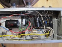
How is the ground connection to the vol. and tone pots made? I can't see it in the various photos.
That ground goes to lug 1 of the vol pot, then on to lug 2 of the tone pot. Giving this area the emery cloth/toothy washer treatment as we speak..
That ground goes to lug 1 of the vol pot, then on to lug 2 of the tone pot. Giving this area the emery cloth/toothy washer treatment as we speak..
That seems OK, but where does it go from lug 1 to reach ground?
It goes to the base of the F&T board mounted filter cap.
Good news, After giving the pots the same treatment as the jacks its definately quieter.
Bad news, that wire was in the correct location [ground of the bias resistor] but in the photo it looked deceiving. It still buzzes a bit but we are getting there!
Actually, it may be fine as before the noise from turning up the tone pot was drowned out by the power supply buzz. Now it appears much louder so the PT buzz is way below that! Hard to tell with it out of the cab but Its a definate big improvement.
Last edited:
Next I'll move the two + wires to the dual cap. I'm going to redo that whole area cause those thin green solid core wires make me nervouse,dont want one breaking during a gig.😱
Its just hard to stuff a thicker wire in that one junction so I'll have to thoroughly de-solder that junction.
Its just hard to stuff a thicker wire in that one junction so I'll have to thoroughly de-solder that junction.
While its out, any observation on that one meg resistor to the pilot light?
The light stays dimly lite when its plugged in but its kind of a 'I got power' indicator. 😀 Doesnt really bug me too much.
The light stays dimly lite when its plugged in but its kind of a 'I got power' indicator. 😀 Doesnt really bug me too much.
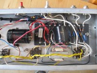
OK, good news. I think I would have put that ground return from the vol. pot to the base of the 10uF cap which is the cathode bypass for V1B, but it would probably not make much difference. (Can try it if you want.)
OK, good news. I think I would have put that ground return from the vol. pot to the base of the 10uF cap which is the cathode bypass for V1B, but it would probably not make much difference. (Can try it if you want.)
I'll give it a whirl! Thanks everybody for walking me through this!
Ok, moved that wire over to the 10uf and didn't hear much change. Its back in the cab now and maybe the vol pot is creating more noise now so I'll move it back next time I remove the chassis.
The power supply noise has been reduced probably 80% from when I received the amp. Probably cant reduce that much more and its probably just normal PS noise now. Very happy!
The power supply noise has been reduced probably 80% from when I received the amp. Probably cant reduce that much more and its probably just normal PS noise now. Very happy!
Attachments
Last edited:
I do have a question about my current bias readings with a 470 ohm resistor.
The calculater says my plate dissipation using the plate current is 14.3watts with a dissipation % of 119.4 . Arent these numbers high? Shouldnt the dissipation be at or below the 12watt rating of the tube and the percentage under 100%?
But using the cathode resistor voltage drop the numbers look fine with 7.2watt dissipation and a 60% dissipation percentage. So which of these two readings do I go by?
I'm just trying to understand what these numbers mean and if its ok to exceed the 12w rating of the tube. I think 6AQ5's are 9.5 watt tubes,not 12 like the 6v6.
My plate current is 43.8ma [21.9 per tube] and cathode current is 46.4ma.
https://robrobinette.com/Tube_Bias_Calculator.htm
Last edited:
Not sure about the figures you are looking at, but in case this helps:
In a pentode, the cathode current is the sum of plate current plus screen current.
Plate dissipation is the plate current times the cathode-to-plate voltage.
Screen dissipation is the screen current times the cathode-to-screen voltage.
If we measure the ground-to-plate voltage, we need to subtract the ground-to-cathode voltage from that to obtain cathode-to-plate voltage. (Similarly for cathode-to-screen voltage.)
Last edited:
My plate current is 43.8ma [21.9 per tube] and cathode current is 46.4ma.Does this look like a good target bias for my 6AQ5's?
I've been playing a Roland JC-120 for the better part of 20 years so this tube terminology is kinda new to me. 😱
I've been playing a Roland JC-120 for the better part of 20 years so this tube terminology is kinda new to me. 😱
Have you measured the cathode-to-ground, plate-to-ground and screen-to-ground voltages in your current set up? If you can give those figures and the resistance of the cathode resistor, we can make some calculations of the dissipation and have a look at where we are on the tube characteristics.
Plate dissipation per tube seems to be 327 x 0.0219 = 7.16 watts
which is well within the 12 watts per tube limit.
Screen dissipation appears to be ((0.0464 - 0.0438)/2) x (272-21.8) = 0.33 watts
You could go warmer on the bias if you want.
which is well within the 12 watts per tube limit.
Screen dissipation appears to be ((0.0464 - 0.0438)/2) x (272-21.8) = 0.33 watts
You could go warmer on the bias if you want.
- Status
- Not open for further replies.
- Home
- Live Sound
- Instruments and Amps
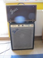
- questions about Fender Musicmaster Bass amp schematic