Do I understand that you have one of these amps coming to you, but do not yet have it? If so, may I suggest you find out how the amp is performing before thinking about modifications.
RF problems with old Fender amps like this are more likely a bad ground connection allowing local AM radio to be picked up. A ferrite bead seems totally unnecessary.
As to shorting that input cap, it does a couple jobs. It blocks DC, such as might result from the output of a effect pedal or wah pedal or some such. Such DC, if present, would go right onto the input tube grid.
ALso, it is part of the tonal structure of the amp. Are you using this amp for bass or guitar?
Will it hurt anything to short the cap? No.
Do I understand that you have one of these amps coming to you, but do not yet have it? If so, may I suggest you find out how the amp is performing before thinking about modifications.
RF problems with old Fender amps like this are more likely a bad ground connection allowing local AM radio to be picked up. A ferrite bead seems totally unnecessary.
As to shorting that input cap, it does a couple jobs. It blocks DC, such as might result from the output of a effect pedal or wah pedal or some such. Such DC, if present, would go right onto the input tube grid.
ALso, it is part of the tonal structure of the amp. Are you using this amp for bass or guitar?
Will it hurt anything to short the cap? No.
Yes,I've got one coming. Don't worry, I plan to leave it stock unless it sounds dissapointing to me. Pretty sure a fuse and speaker are on my to do list.
Question, do you advise against removing that .0047 cap? It seems to be the most common mod to these [with a one meg grid stopper].
My reasoning is why not use a ferrite bead as a jumper, no harm done and a potential [albeit slight] benefit.
I do advise against removing it. You can tack a wire across it when you get there just to see if it affects the sound of the amp. A lot of mods are common, and a lot of those common mods are done for specious reasons. Someone rationalizes that such and such effect would be diminished by some mod. never mind that the effect would be outside the audio range or some such.
if you remove it, I see no benefit adding the bead. it won't affect anything the amp is likely to do. If you wasn't to stick one in there anyway, yes it will not hurt anything. But pardon my being a smart Alec, but might as well install garlic cloves to ward off elephants. The amp really doesn't have the bandwidth for RF to be much of a problem. As I mentioned earlier, the real RF problem with amps like this is that which occurs because the input jack loses a solid ground connection.
To me the DC blocking aspect of it is important, especially in this day and age of a huge pile of effect pedals on a "pedal board" in front of the amp, especially if older FX pedals are used.
But pardon my being a smart Alec, but might as well install garlic cloves to ward off elephants. The amp really doesn't have the .
😀 Now that was funny!
Point taken!
To me the DC blocking aspect of it is important, especially in this day and age of a huge pile of effect pedals on a "pedal board" in front of the amp, especially if older FX pedals are used.
I will be using this with guitar and a 10 pedal board, so thanks for your input!
Ok, the amp arrived and she works great.Instantly greeted me with a beautiful Fender clean tone. I thought I would be doing a bunch of the recommended mods like the tone control mod,hasselbrock mods,jumpering the RF blocking cap etc. But I kinda doubt it now.Really a great,clean little handwired Fender amp.😎
There is some power supply noise that remains constant regardless of the vol/tone settings. I'm hoping that new filter caps will help here.
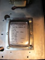
There is a new PT in this thing,I'll include a photo of the specs. Looks to be the same specs as stock but its much thicker [2x more layers] for better cooling?
Question #1:Is this a good,suitable PT for this amp?
Things I need to address:
1-Fuse [got this covered]
2- Electrolytic caps. I ordered a complete set of F&T caps,havn't arived yet.
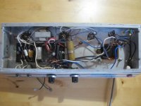
3- Question # 2 why has the 220ohm restistor been replaced with those green ones? The large one is 640ohm and it is in series with another one that is unmarked? This is not original and I have a 250ohm block type on hand to replace those, but I would like opinions first as maybe there is a reason that 640ohm was chosen with the new PT?
More questions to come but this really would address most of what I want to change with this amp. Really, just reducing the power supply hum would make me happy.
There is some power supply noise that remains constant regardless of the vol/tone settings. I'm hoping that new filter caps will help here.
There is a new PT in this thing,I'll include a photo of the specs. Looks to be the same specs as stock but its much thicker [2x more layers] for better cooling?
Question #1:Is this a good,suitable PT for this amp?
Things I need to address:
1-Fuse [got this covered]
2- Electrolytic caps. I ordered a complete set of F&T caps,havn't arived yet.
3- Question # 2 why has the 220ohm restistor been replaced with those green ones? The large one is 640ohm and it is in series with another one that is unmarked? This is not original and I have a 250ohm block type on hand to replace those, but I would like opinions first as maybe there is a reason that 640ohm was chosen with the new PT?
More questions to come but this really would address most of what I want to change with this amp. Really, just reducing the power supply hum would make me happy.
Attachments

Ok, new fuse installed but I've encountered my first minor problem. I had to extend the wire from the fuse to the switch so I loosened the vol/tone assembly to get at it. Works great but now my switch doesnt click on and off, its just always on when I plug it in now. I guess I could live with this as the switch isnt a standby so the tubes get slammed anyway once you plug in,but it would be nice to get the 'click' on off back.
Anybody familiar with these old pot mounted Fender switches?
Anybody familiar with these old pot mounted Fender switches?

Someone changed the 220 ohms to something else in an attempt to bias the amp differently, either to accommodate a particular tube or to change tube types. The new PT may or may not be the cause of that adjustment.
Someone changed the 220 ohms to something else in an attempt to bias the amp differently, either to accommodate a particular tube or to change tube types. The new PT may or may not be the cause of that adjustment.
Hi Enzo, how can I figure out why the value was changed? Sorry, I can solder fluently but I'm not a tech..
The tubes are 6AQ5,as original. I tried some NOS tubes and it is power supply noise,not affected by the tubes.
Last edited:
REvert the amp to stock is probably a good place to start.
You'll never figure out WHY, you can only come up with possible reasons. The circuit is cathode biased, to the cathode resistor sets how hot the tube runs.
Here is the schematic to go with your layout.
http://bmamps.com/Schematics/fender/musicmaster_bass_schem.pdf
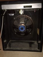
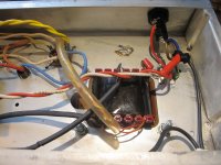
But those use 6V6. Yours has 6AQ5s??? Looking at your chassis I see the two power tube sockets are different sizes. The smaller one nearer the power transformer looks to have been mounted in a larger hole: note the empty mounting holes next to it, and the screws are notched into the edge of the chassis hole. The 6AQ5 is equivalent to the 6V6, but not identical. I would wager that someone rebuilt the original 6V6 amp into a 6AQ5 version. But I could be wrong. I myself have never seen a 6AQ5 version of this model, but that doesn't mean they don't exist.
If 200 ohms runs the tubes too hot, we increase it, but it seems like a good starting point.
You'll never figure out WHY, you can only come up with possible reasons. The circuit is cathode biased, to the cathode resistor sets how hot the tube runs.
Here is the schematic to go with your layout.
http://bmamps.com/Schematics/fender/musicmaster_bass_schem.pdf
But those use 6V6. Yours has 6AQ5s??? Looking at your chassis I see the two power tube sockets are different sizes. The smaller one nearer the power transformer looks to have been mounted in a larger hole: note the empty mounting holes next to it, and the screws are notched into the edge of the chassis hole. The 6AQ5 is equivalent to the 6V6, but not identical. I would wager that someone rebuilt the original 6V6 amp into a 6AQ5 version. But I could be wrong. I myself have never seen a 6AQ5 version of this model, but that doesn't mean they don't exist.
If 200 ohms runs the tubes too hot, we increase it, but it seems like a good starting point.
REvert the amp to stock is probably a good place to start.
You'll never figure out WHY, you can only come up with possible reasons. The circuit is cathode biased, to the cathode resistor sets how hot the tube runs.
Here is the schematic to go with your layout.
http://bmamps.com/Schematics/fender/musicmaster_bass_schem.pdf
But those use 6V6. Yours has 6AQ5s??? Looking at your chassis I see the two power tube sockets are different sizes. The smaller one nearer the power transformer looks to have been mounted in a larger hole: note the empty mounting holes next to it, and the screws are notched into the edge of the chassis hole. The 6AQ5 is equivalent to the 6V6, but not identical. I would wager that someone rebuilt the original 6V6 amp into a 6AQ5 version. But I could be wrong. I myself have never seen a 6AQ5 version of this model, but that doesn't mean they don't exist.
If 200 ohms runs the tubes too hot, we increase it, but it seems like a good starting point.
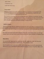
Ok, I found the value of the second bias resistor,its 470ohm. So what is 470ohm + 680ohm in series? I'd like to replace it with one of the correct value.The seller included a repair receipt from the tech who installed the PT. It explains alot.Aparrantly what ever value this is has biased the tubes at 40ma.
Yes the amp uses 6AQ5 power tubes.The earlier Fender Musicmaster Bass amps all came fitted with 6AQ5's. One tube socket has been replaced in the past on this amp.
Good news, I re-did the heater wires and it cut the noise in half at least already,so I feel positive about the new filter caps solving the rest. We will see!
Attachments

I suggest you measure the 6AQ5 bias voltage with the current resistors in place before you change them. Tell us what it is. And measure the actual total resistance of the 2 bias resistors in series. Then we know enough to confirm the bias current, and then decide if it needs changing.
Last edited:
I suggest you measure the 6AQ5 bias voltage with the current resistors in place before you change them. Tell us what it is. And measure the actual total resistance of the 2 bias resistors in series. Then we know enough to confirm the bias current, and then decide if it needs changing.
Sorry if I'm a bit of a newb [not really a tech]. Where should I take that bias voltage measurement?
The resistors are 680ohm + 470ohm in series, so a bit over 1k.
Look at the schematic ENZO posted. There is a voltage label of 16v at the junction of the 6v6 cathodes and the 220R bias resistor. This equates to 73 mA thro the resistor (ohms law) or 36mA per tube.
But you don't have 6v6 tubes, or the original PT.
And the amp has been set up by someone in the business.
So don't change those resistors until you have a reason.
For every voltage labelled on the schematic you should take the voltage for your own amp and record these for a baseline (print off the schematic and write in your own numbers on it).
Do this first for any tube amp you get your hands on before any attempts to modify or repair.
Ohms law is your light in the darkness of guess and conjecture.
The amp is cathode biased, and in such amps, the cathode voltage IS the bias voltage.
So measure the voltage at the cathode - ie the voltage across your two series resistors, then ohms law will tell you the current through the tubes.
So measure the voltage at the cathode - ie the voltage across your two series resistors, then ohms law will tell you the current through the tubes.
Ok, I have a pin 2 reading of 33.8v, on the schematic it should be 16v. Not sure what this or the ohms law calculation tells me though? 
oltage (V) = Current (I) * Resistance (R)
Power (P) = Voltage (V) * Current (I)
Enter any two known values and press "Calculate" to solve for the others.
Voltage (V)
33.8
Volts (V)
Current (I)
0.0338
Resistance (R)
1000
Power (P)
1.14244
Watts (W)
oltage (V) = Current (I) * Resistance (R)
Power (P) = Voltage (V) * Current (I)
Enter any two known values and press "Calculate" to solve for the others.
Voltage (V)
33.8
Volts (V)
Current (I)
0.0338
Resistance (R)
1000
Power (P)
1.14244
Watts (W)
Last edited:
OK. So your amp is biased very cold (high bias voltage keeping tube current low).
Before warming it up we also need to know what is happening at the "top" of the tube ie Anode and screen voltages.
The data sheet for the 6AQ5 recommends these not exceed 250v.
If the new PT is designed for a 6v6 circuit then your power supply will exceed this and the tubes may have been biased cold to compensate - maybe 😕
(The anode/screen voltages can be measured from ground and then cathode voltage subtracted, or directly measured from cathode to anode/screen - whichever is physically safer. Don't get bitten😱)
So take these new measurements so we can see the whole tube picture and figure out what to do next 😉
Sure thing, which pins are anode/screen? G1/G2/G3?OK. So your amp is biased very cold (high bias voltage keeping tube current low).
Before warming it up we also need to know what is happening at the "top" of the tube ie Anode and screen voltages.
The data sheet for the 6AQ5 recommends these not exceed 250v.
If the new PT is designed for a 6v6 circuit then your power supply will exceed this and the tubes may have been biased cold to compensate - maybe 😕
(The anode/screen voltages can be measured from ground and then cathode voltage subtracted, or directly measured from cathode to anode/screen - whichever is physically safer. Don't get bitten😱)
So take these new measurements so we can see the whole tube picture and figure out what to do next 😉
Attachments

Last edited:
- Status
- Not open for further replies.
- Home
- Live Sound
- Instruments and Amps
- questions about Fender Musicmaster Bass amp schematic