spdif output and input
Ecdesigns, i found some ideas for spdif:
Output from SAA 7220:
http://www.diyaudio.com/forums/attachment.php?s=&postid=764002&action=thumb&stamp=1131660111
Spdif Input in dac: (CS8414)
http://www.diyaudio.com/forums/attachment.php?s=&postid=795146&action=thumb&stamp=1135100334
Thread:
http://www.diyaudio.com/forums/showthread.php?s=&threadid=67247&perpage=10&highlight=&pagenumber=1
Is it an idea to load the same value resistors and use a diy ringcore pulse transformer too in the CDP, this for right impedance match on SAA7220? Thanks!
DEM clock synchronizing / SPDIF
Hi, Tubee
Thanks for your reply [post#279]
> The analog mainboard makes all connections between the modules, contains LCL filters and the DEM (Dynamic Element Matching) synchronizing clock circuit, BCK buffers and a separate 5V power supply. The DEM clock has been modified again, so wait until I post final schematics.
The modules that are placed on the analog main board are separate, the DEM clock synchronizing circuit is part-of the analog mainboard. But I can design a small circuit board, only holding the DEM clock synchronization circuit.
> The DIR1703 would be a good choice for the octal D-I dac, the DIR1703 with the SpAct (Sampling period Adaptive controlled tracking) seems to have a clock jitter of only 75pS, compared to 200pS for both CS8412 and CS8414. Since it has no RS422 input, a differential receiver chip needs to be added. I am planning to make modules for all 3 types. Currently I am using the CS8412.
> I plan to use the PCM2706 from TI for USB to I2S conversion, It's another separate module that plugs-in the digital mainboard, or can be used separately (like all modules of the octal D-I DAC).
[post#281]
About the SPDIF question, why not connect the DS8922 RS422 driver input directly to pin 14 (DOBM) of the SAA7220 (without the schmitt trigger circuit). Then you have a differential RS422 output driver with only one chip, and don't have to worry about pin 14 loading. On the receiving side you can experiment with the circuit I posted earlier.
spdif
Ok thanks Ecdesigns for answering.
I will wait for the dem reclock schematic then, but will put the Kwak 7 in first.
For the Spdif will search a DS9822, its a pitty i bought a 74HCT14 this afternoon for 3 euro's! And not even a Philips!
I have a cs8414 waiting to be used in a dac, but in meantime better ones are seeing daylight.
Keep going with the very good work on the modular designed D-I dac. Still i am very curious on its sound.
balanced versus single ended
Just a curious question. I know this DAC is a balanced design at the digital and analogue stages, but most of us don't own balanced preamp or amp. So if we use the RCA single ended output of the DAC, does this defeat the purpose of balanced design? Or do we still get some benefit of the balanced design (eg, noise cancelllation) even though we are using the single ended output?
Just a curious question. I know this DAC is a balanced design at the digital and analogue stages, but most of us don't own balanced preamp or amp. So if we use the RCA single ended output of the DAC, does this defeat the purpose of balanced design? Or do we still get some benefit of the balanced design (eg, noise cancelllation) even though we are using the single ended output?
Finally ready, the analog mainboard
Hi,all
Look what I found,
Mainbordus analogus maximus, a rare species of the octal D-I DAC family .
.
Sorry about that") ,
,
but I'm in a good mood since the octal D-I DAC core is ready and is finally working now. The added photograph shows the Analog mainboard with all modules added. I will post some more photographs of the analog mainboard without modules, and the solder side.
Did it work the first time? no actually it didn't. After checking all power supply voltages and I2S signals, I placed the remaining modules on the analog mainboard and switched-on. Nothing, checked voltages again, they were ok, checked the I2S signals, all there. Then I removed the differential OP-amp modules and connected a resistor on the DAC outputs, still nothing. Then I had another quick look at what was left of the prototype board, it couldn't be, or could it? yes I swapped DATA and BCK signals on the analog mainboard  . After some thoughts about how to fix this in an elegant way , I decided to swap the signals on both Quad-DAC modules. Put everything together, and switched-on, it finally worked like a charm.
I will run some more tests to see if things can be optimized. PCB's will need some minor modifications, then this major part of the octal D-I DAC project is finally ready
Hi,all
Look what I found,
Mainbordus analogus maximus, a rare species of the octal D-I DAC family
.Sorry about that
,but I'm in a good mood since the octal D-I DAC core is ready and is finally working now. The added photograph shows the Analog mainboard with all modules added. I will post some more photographs of the analog mainboard without modules, and the solder side.
Did it work the first time? no actually it didn't
. After checking all power supply voltages and I2S signals, I placed the remaining modules on the analog mainboard and switched-on. Nothing, checked voltages again, they were ok, checked the I2S signals, all there. Then I removed the differential OP-amp modules and connected a resistor on the DAC outputs, still nothing. Then I had another quick look at what was left of the prototype board, it couldn't be, or could it? yes I swapped DATA and BCK signals on the analog mainboard . After some thoughts about how to fix this in an elegant way , I decided to swap the signals on both Quad-DAC modules. Put everything together, and switched-on, it finally worked like a charm.I will run some more tests to see if things can be optimized. PCB's will need some minor modifications, then this major part of the octal D-I DAC project is finally ready
Attachments
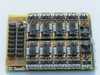
Analog mainboard without modules
Hi, MGH
Thanks for your replies [post#280,#284]
> Circuit boards: I am planning to use glass epoxy boards with thick gold-plated copper tracks and a blue laquer anti-solder mask.
> The octal D-I DAC is a fully balanced design, starting with the differential SPDIF input to prevent jitter. Then a differential DAC arrangement (4 non-inverted DAC outputs and 4 inverted DAC outputs) to cancel out some more interference AND cancel-out DC offset, so a grounded grid and DC coupled signal (OP-amp) can be used. The differential OP-amp and Tube amplifiers are necessary to combine the inverted and non-inverted signals into a non inverted signal with twice the amplitude.
The tube stage in addittion has a differential output setup (2 cathode followers) for a fully equal balanced "load" on the differential amplifier, this significantly increases stability and symmetry, reducing distortion and increases CMMR.
Don't worry about the single ended RCA connections, my set is also single ended. So I am not going to use a balanced output either.
I have added another photograph of the analog mainboard without modules placed.
Attachments
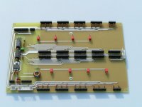
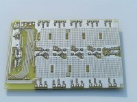
Analog mainboard solder side
Hi, tubee
Thanks for your reply [post#283]
> New DEM clock schematics will be posted soon, it's no pitty you bought the 74HCT14, if you put 2 schmitt trigger inverters between the SAA7220 and the DS8922 (so the signal is not inverted) you can increase slew rate.
> I am curious about the Kwak 7 oscillator. I had a look at the schematics, what frequency does it generate and how is it connected? I have seen some spectrum analysis of the Kwak 7 oscillator on the internet, that showed a strange continuously varying spectrum.
> I will do some testing with the DIR1703, specifications look good
I added another photograph of the analog mainboard (solder side)
Attachments
Thanks ecdesigns.
Good to hear everything is comming together nicely.
Regarding the PCB, have you conidered a black lacquered PCB instead of blue? I've seen black PCB board with gold plated copper tracks - I must say it really looks nice that way, and it's rare to have this combination. It really would stand out. Anyway, it's a minor point, but I'd thought I give my 2 cents on the look of the PCB.
BTW, the board with all the chips look very well thought out with efficient use of space - very professional.
Hi ecdesigns,
very nice work. I am very enjoying to read this thread.
I would be satisfy also with this PCBs.
Will be in NOS DAC using also 74HC161?
I ordered by mistake 50 pieces of 74HC161 Philips, instead 50 resistors.
Would be here any improvements, if we put copper EMI (3M) shielding tape on ICs?
I can ask for lower prizes (group buy) for TDA1541A/R1, if will be interest to do this. I got mine for 15US$ per piece.
I guess that best for 470pF would be silver-mica capacitor.
regards
hallo ecdesigns and all .
I also like very much this thread and will be interested in the realization or the DAC ... I am thinking of a "quad" version for now but ready to change my mind in future .
Would be nice to have a group buy for pcb also .
By the way I have not clear in mind how the analog signals are mixed at the output ... and ... are in the last pictures of the "analog board" op amps used for the outputs ready on the board ??
Thanks and compliments for a nice work
size of pcb, kwak 7
Hi Ecdesigns
I tried 2 clocks, and prefer kwak 7 for soundquality. Delivers good bass (which i like), but the other clock i tested gave a slightly more detailed sound. Matter of taste. The scope didn't show very nice waveforms on Kwak's, but i think its the jitterreduction (in special time-shifting fenomenons) where the kwak 7 is better in compared to the original crystal of cdp imo. But for me what counts is the sound.
The Kwak 7 can have cristals to about 25 mHz, i connect the output into Xin of SAA7220, but want to try it in Xin of SAA7210 too.
The mainboard design looks very nice! What dimension has it ?
An error in wiring is easily made, i know that by now...
Hi, a333bt
Thanks for your compliments [post#289]
> The octal D-I DAC can have both 74HCT161 or 74HC161, the 74HC161 chip's you accidently bought are fine.
> EMI shielding tape can be used on the IC's, but it has to be connected to ground. The majority of interference however is generated / picked-up by the tracks.
This octal D-I DAC core is a basic setup to work with, it can be modded / improved as you like. By using the same setup as I have, you are certain it will work correctly as all (sub) components have been tested.
> Depending on how many people want to build this (octal) D-I DAC, group buy of the TDA1541A could be very interesting.
> As you can see on the analog mainboard photographs, the 470pF capacitors are removed from the DAC modules. They are now placed on the analog mainboard and used only to feed the 176.4 KHz DEM clock into the 8 TDA1541A's (they are no longer used as part of a oscillator, so stability becomes less important). I used high quality polypropylene capacitors from WIMA, they work just fine.
Analog output circuit
Hi, stefanobilliani
Thanks for your compliments [post#290]
> The octal D-I DAC can also be modified to a dual or quad D-I DAC, just by placing DAC modules in their correct location on the analog mainboard. On the photograph, upper DAC modules from left to right: 2,4,6,8. Lower DAC modules from left to right: 1,3,5,7.
I left 4 identical DAC modules on one "Quad DAC" circuit board without separating them. The output amplitude will vary between 2, 4 or 8 DAC version, so modification of the output attenuator is necessary. If you are going to build this DAC, I can only reccomend to go for the octal version, the sound improvement due to the higher resolution is absolutely worth it.
The analog current outputs of the DAC modules are connected in two groups of 4 (one group non-inverted D1, D3, D5 and D7, the other group inverted as they receive inverted digital DATA signal ND2, ND4, ND6 and ND8).
Then each of these groups is fed to a I/V converter (2 per channel) using high quality OPA627 OP-amps (2 SMD versions on an adapter board with heatsink) in a optimized circuit (perfect squarewave shaped steps at the output R=590R, C=100pF). So then we have 2 stepped analog output signals of approx. 8Vpp max. One non-inverted, one inverted.
These two signals are then fed into a optimized unity-gain differential amplifier (R=1K96, C=330pF), using a DIP OPA627 version. The output signal of the diff amp is twice the input signals (16Vpp), yes 16Vpp! the virtual LSB (bit19) is approx. 30uV.
> The two small diff-amp modules on the photograph contain this complete circuit. So this analog mainboard including modules is already a fully functional DAC. I/V converter outputs are also routed to the analog output connector.
If you only want to use the OP-amp output, just add a attenuator (R/R) to obtain the correct output voltage, and route it to the RCA socket. But if you want to add the differential tube output stage as well, this tube output stage can be connected to the I/V outputs. So both OP-amp and tube output stage work simultaneously. Then you can select OP-amp, tube or mixed mode (schematics of attenuator / mode selector will follow).
New timing-chain module / power metal film resistors
Hi, tubee
Thanks for your compliments [post#291]
> The analog mainboard dimensions are 172mm X 242mm X 30mm (6.77" X 9.35" X 1.18"), OPA627 heatsinks included.
Today I redesigned the timing-chain module (improved ground plane and added a 74HC08 local buffer for both WS and DATA). And I corrected the DAC module layout (swapped DATA and BCK lines).
I also tested a ringcore based pulse transformer from Farnell (SPDIF), and it seems to work very well. So now I can proceed with the first audio interface module (CS8412).
I also received very nice 1% power metal film resistors from Conrad electronics today, these are intended for the differential tube output stage. I plan to compare these with the carbon composite resistors (Riken-Ohm) that maxlorenz preferred. I am very interested in how these Riken-Ohm resistors influence sound and noise level.
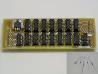
I also added a photograph of the new timing-chain module and the power metal film resistors, the small resistors are common 0.6W metal film resistors for comparison.
Hi, tubee
Thanks for your compliments [post#291]
> The analog mainboard dimensions are 172mm X 242mm X 30mm (6.77" X 9.35" X 1.18"), OPA627 heatsinks included.
Today I redesigned the timing-chain module (improved ground plane and added a 74HC08 local buffer for both WS and DATA). And I corrected the DAC module layout (swapped DATA and BCK lines).
I also tested a ringcore based pulse transformer from Farnell (SPDIF), and it seems to work very well. So now I can proceed with the first audio interface module (CS8412).
I also received very nice 1% power metal film resistors from Conrad electronics today, these are intended for the differential tube output stage. I plan to compare these with the carbon composite resistors (Riken-Ohm) that maxlorenz preferred. I am very interested in how these Riken-Ohm resistors influence sound and noise level.
I also added a photograph of the new timing-chain module and the power metal film resistors, the small resistors are common 0.6W metal film resistors for comparison.
Attachments
Hi Ecdesigns, i am beginning to get water in my mouth with all those nice designed pcb's.
I have informed at my parts store, the DS8922N will cost me about 6 euro's. Will order it tomorrow.
Btw, what cd-engine do you use?
This chap (and a very kind one) modified a CD880 based cd-engine.
http://home.hccnet.nl/r.r.meijer/cdd oud.html
I have informed at my parts store, the DS8922N will cost me about 6 euro's. Will order it tomorrow.
Btw, what cd-engine do you use?
This chap (and a very kind one) modified a CD880 based cd-engine.
http://home.hccnet.nl/r.r.meijer/cdd oud.html
Dear ecdesigns:
I am SURE that there will be ENORMOUS interest for your PCB's and also for TDA1541A's group buys.
Even better, with your kind aproval of course, maybe someone will be interested in creating a KIT GB (for us, beginners that have a pain to source all parts )
It would be very interesting to hear your opinion as you seem to be a good listener
"Let the force be with you"
M
> Depending on how many people want to build this (octal) D-I DAC, group buy of the TDA1541A could be very interesting.
I am SURE that there will be ENORMOUS interest for your PCB's and also for TDA1541A's group buys.
Even better, with your kind aproval of course, maybe someone will be interested in creating a KIT GB
(for us, beginners that have a pain to source all parts )I am very interested in how these Riken-Ohm resistors influence sound and noise level.
It would be very interesting to hear your opinion as you seem to be a good listener
"Let the force be with you"
M
parts
And when we order a great bulk of parts, we can get the financial aspect more in hand. Besides that it is possible to order parts made from the "best" manufacturers.
have a pain to source all parts
And when we order a great bulk of parts, we can get the financial aspect more in hand. Besides that it is possible to order parts made from the "best" manufacturers.
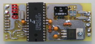
Digital Audio Interface module #1, listening tests
Hi all,
Another project update, The first digital audio interface module using the CS8412 / CS8414 (adapter socket needed) is ready. I added a photograph. The module has it's own power supply regulator and is double filtered using 10nF muRata LCL filters. Decoupling cap's are placed directly next to the IC's powersupply pin's, SMD decoupling cap's and some more SMD resistors on the solder side. It runs on approx. 8V DC.
PLL loop filter resistor (SMD) and cap are placed very close to the chip, minimizing jitter.
It has a rincore based 1:1 pulse transformer on-board (Farnell part nr. 108-8707), so it can be directly connected to both a differential or single ended socket.
Modes can be selected with 5 jumpers, an on-board indicator LED lights when the SPDIF signal is received correctly.
Outputs are: WS, BCK, DATA, ERF (Error Flag) and +5V.
The module is compact, and layout is optimized for best performance.
Sound impressions of the new setup.
The new analog mainboard and digital audio interface module, the compact setup, extensive power supply filtering (LCL filters), the separare power supply regulators and DEM clock syncing and the power metal film resistors in the differential tube output stage have made another massive impact on sound quality. The listening test was carried out using the mixed mode, that has become my absolute favorite.
I can try to describe how it sounds now, just as an indication. The sound completely comes alive, it sparkles at a pitch-black stage. Even "dull" classic music suddenly comes alive in a way I never dreamed possible, sudden peaks in the music make you realize what dynamic range this octal D-I DAC has, you almost jump of your chair. I spend hours listening to it, trying to find a weak spot.
I threw all possible music at it, classical, vocal, jazz, pop, instrumental, chesky recordings, also selected "difficult" music that immediately makes "problems" audible. For instance absolute clarity of high-pitch voices, speed and accuracy / impact of bass, music with very critical midrange, natural reproduction of s-sounds, natural reproduction of instrument's acoustic properties, "complex" music with lots of instruments. Finally I called it a day, as it passed them all. And these results were obtained with a basic "test" setup, imagine what can be achieved by fine tuning and modding...
by the way, I will answer your posts as soon as possible.
Attachments
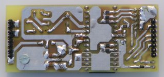
SPDIF module #1 solder side
Hi, tubee
Thanks for your reply [post#295]
Currently I am using a modified Sony CDP-CX355. It can hold 300CD's, so I can swap quickly between (test) CD's for comparison.
But I also use a mac computer with CD's stored on a high capacity external harddisk, using lossless compression. Since the USB to I2S interface is not ready yet, I use a USB to SPDIF converter for the moment.
I have added a photograph of the SPDIF interface module #1 solder side
Attachments
- Home
- Source & Line
- Digital Line Level
- Building the ultimate NOS DAC using TDA1541A