regarding those LDOs, most of them are very good and ecologically clean for consumer electronics. that is what they have been designed for.
low noise is not the single most important parameter for PS. low enough and flat in audio range output impedance, and related load transient response matters very much here. this has been discussed, simulated and measured. here I attach a sim by Pavel Pogodin, posted on another forum for 50kHz/10mA load). I am not claiming that this is a final truth and now everyone should do like this, but practical results are clearly in favour of discrete regs for audio as well.
Any chance that you know of a tested and stable version of Pavel's circuit that uses an LM4562, NE5532/4, NJM4580 or NJM2068? I am looking for a practical way to try the general idea without trying to redesign it or order new LTC6228 op amps.
Let me just say this about LT3042/LT3045, it reminds me of when someone asked what about using a battery for AVCC. Same thing here, people have tried it. People who tried LT3045, Jung (with sense connected at load), opamp buffer, etc., preferred the latter two over LT3045. Was it because of the ceramic output cap, the nonlinearity of which is discussed in LT3045 datasheet? Don't know, but it shouldn't be too hard to swap some ceramic output caps and see if the sound changes. If not that then maybe its something else. Again, dunno. Only know it wasn't a favorite in uncontrolled listening tests. Since that's anecdotal, non-scientific information, the only advice I feel comfortable giving is: Try it if you want, but you might want to try opamp buffers or maybe a Jung before you make a final decision.
Last edited:
kozard,
The circuit Pavel simmed looks sorta similar to a Jung series regulator. Basically, an opamp for the error amplifier and a separate series pass element. There is a also a Jung shunt regulator, which some claim for audio use is superior to the Jung series pass version.
The circuit Pavel simmed looks sorta similar to a Jung series regulator. Basically, an opamp for the error amplifier and a separate series pass element. There is a also a Jung shunt regulator, which some claim for audio use is superior to the Jung series pass version.
Last edited:
kozard,
The circuit Pavel simmed looks sorta similar to a Jung series regulator. Basically, an opamp for the error amplifier and a separate series pass element. There is a also a Jung shunt regulator, which some claim for audio use is superior to the Jung series pass version.
This one? https://refsnregs.waltjung.org/UnivReg_122714.pdf
Or the original: https://refsnregs.waltjung.org/AX_WJ_Interview.pdf
The first paper you found is for the Jung shunt regulator. The schematic in the interview article is also a shunt version. Basically, there is a current source that feeds power into the regulator. An error amplifier shunts some of the input current to ground so as to regulate the output voltage.
The Jung series regulator is also sometimes referred to as a Jung-Didden regulator. An example would be the version for which a PCB is available from the diyaudio store. There is also a thread dedicated to it. Schematic attached below.
The Jung series regulator is also sometimes referred to as a Jung-Didden regulator. An example would be the version for which a PCB is available from the diyaudio store. There is also a thread dedicated to it. Schematic attached below.
Attachments
Any chance that you know of a tested and stable version of Pavel's circuit that uses an LM4562, NE5532/4, NJM4580 or NJM2068? I am looking for a practical way to try the general idea without trying to redesign it or order new LTC6228 op amps.
perhaps better you ask Pavel yourself. I suppose the opamp used is indispensable in the particular design.
as I mentioned earlier, for AVCC and opamp PS I used Nazars shunts: ES9038Q2M Board
there are enough descriptions and measurements found elsewhere. including the link I provided you.
Let me just say this about LT3042/LT3045, it reminds me of when someone asked what about using a battery for AVCC. Same thing here, people have tried it. People who tried LT3045, Jung (with sense connected at load), opamp buffer, etc., preferred the latter two over LT3045. Was it because of the ceramic output cap, the nonlinearity of which is discussed in LT3045 datasheet? Don't know, but it shouldn't be too hard to swap some ceramic output caps and see if the sound changes. If not that then maybe its something else. Again, dunno. Only know it wasn't a favorite in uncontrolled listening tests. Since that's anecdotal, non-scientific information, the only advice I feel comfortable giving is: Try it if you want, but you might want to try opamp buffers or maybe a Jung before you make a final decision.
As far as using a battery it is not so simple. So if you tried a battery and did not like the results then the attached waveforms might start to help explain why. (They are just a beginning, however.)
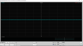
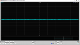
For example, the attached images (1 & 2) show how clean AVCC_R and VCC_A can be when the board is powered with a battery (and there are OS-CON across the various individual supply pins on the board.) [No AMS1117-3.3, no LM7805.]
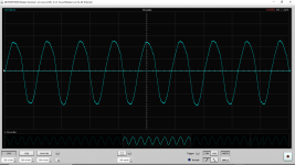
Next the attached images (3 & 4) show what happens when the optical is locked (but no signal, idle). #3 is AVCC_R and #4 is VCCA. Essentially the input power can be very clean but something on the board is a strong LF noise generator. It appears to be roughly 85 Hz not 60 Hz. [I am not saying any of this is at all surprising, I just post this reply to be informative regarding the fact that people apparently tried batteries and did not like the result. Most of you are probably well aware that this will occur.]
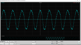
The last attached image (5) shows what happens when locked to coax and the DVD player goes from idle to playing music.
So don't think running on battery means low noise on the supplies. Like regulators it might be necessary to include multiple independent batteries, deal with power supply sequencing and even use LDOs on the offending LF noise generating pin(s).
It will take more work to find out where it is coming from. (ES9038Q2M, ATTINY, etc. I don't think it is the 1G04 CMOS inverter (5 pin SOT) for the optical since it occurs with no optical.) If anyone knows which pin (ES9038Q2M DVDD or ATTINY VCC or ?) please let me know.
Attachments
-
 VCCA_R Battery Power J2 Installed Optical Cable Disconnected Not Locked.png42.6 KB · Views: 199
 -
 AVCC Battery Power J2 Installed Optical Cable Disconnected Not Locked.png52.9 KB · Views: 188
 -
 VCCA_R Battery Power J1 Installed Optical Locked.png98.9 KB · Views: 207
 -
 AVCC Battery Power J1 Installed Optical Locked.png110.1 KB · Views: 192
 -
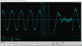 AVCC Battery Power J2 Installed Coax Locked DVD Player Turned On Going From Idle to Playing.png118.7 KB · Views: 186
Last edited:
When coax/optical is locked there may be something going on with the DPLL hunting around to keep it locked, dunno. Might be interesting to see if the same symptoms appear with a different coax/optical source and or if changing DPLL_Bandwidth has any effect. With coax, ground noise could possibly be an issue since the dac board doesn't have an isolation transformer. Did I say I encourage experimenting to help find clues?
EDIT: Regarding trying multiple independent batteries, some of the iancanada crowd are doing that. Seems they found adding caps to batteries helped sound quality, maybe some combination of super-caps and batteries. They had already tried just super-caps and just batteries. Personally, don't find that stuff is necessary and neither do any of the serious dac manufacturers that I am aware of.
EDIT: Regarding trying multiple independent batteries, some of the iancanada crowd are doing that. Seems they found adding caps to batteries helped sound quality, maybe some combination of super-caps and batteries. They had already tried just super-caps and just batteries. Personally, don't find that stuff is necessary and neither do any of the serious dac manufacturers that I am aware of.
Last edited:
I don't know if experimenting with battery power will help me to identify and understand the noise characteristics of each pin on the board or not. At least everything else is not buried in AMS1117 generated noise while I work on the replacement regulators, references and buffers.
The approx 42.5 to 45 Hz spur is -124 dB down on the output.
The approx 85 to 90 Hz is -127 dB down on the output.
The approx 42.5 to 45 Hz spur is -124 dB down on the output.
The approx 85 to 90 Hz is -127 dB down on the output.
Last edited:
When coax/optical is locked there may be something going on with the DPLL hunting around to keep it locked, dunno. Might be interesting to see if the same symptoms appear with a different coax/optical source and or if changing DPLL_Bandwidth has any effect. With coax, ground noise could possibly be an issue since the dac board doesn't have an isolation transformer. Did I say I encourage experimenting to help find clues?
Sure. In this case I started with optical and the coax results are very close to identical. Don't have access to change DPLL/register 12 or other ES9038Q2M registers yet. I do have various micro-controllers but I don't want to go down that rabbit hole right now.
Last edited:
EDIT: Regarding trying multiple independent batteries, some of the iancanada crowd are doing that. Seems they found adding caps to batteries helped sound quality, maybe some combination of super-caps and batteries. They had already tried just super-caps and just batteries. Personally, don't find that stuff is necessary and neither do any of the serious dac manufacturers that I am aware of.
Sure. I am not saying that it is necessary or that it is the way to go.
I just thought I would give it a try while working on the replacement regulators, references and buffers. After all I had the batteries sitting here and perhaps I can more easily identify and pin-point the other noise sources on this board if I get rid of the huge AMS1117 noise that buried other noise sources. The other approaches will likely involving ordering stuff and I like to try what is here already first. Maybe I end up with a better result (with the replacement regulators, references and buffers) with what I learn with the battery power experiments.
Also this way I don't have 60Hz line power and transformers everywhere. (And grounding questions. The laptop is also on battery power.)
Also it is a mobile part
")
Last edited:
EDIT: Regarding trying multiple independent batteries, some of the iancanada crowd are doing that. Seems they found adding caps to batteries helped sound quality, maybe some combination of super-caps and batteries. They had already tried just super-caps and just batteries. Personally, don't find that stuff is necessary and neither do any of the serious dac manufacturers that I am aware of.
I don't understand the purpose of super-caps here. I searched for Iancanada and super-caps and I ended up looking at Panasonic datasheets that specify less than or equal to 75Ohms internal resistance at 1kHz. That is 75Ohms, not 75mOhms. What is the reason they are using them? If I needed a small battery backup for a low power micro-controller maybe I would look at a super-cap.
Edit: Ok. I read some more in that thread and see some Maxwell Ultracapacitors that cost more than this DAC board and in the very large values approach the ESR of one of my 5 cent OS-CON capacitors.
Err... so... not for me. I don't see the point. I will stick with my quick and dirty battery to listen to this while I work on the replacement regulators, references and buffers.
Last edited:
They tried using supercaps instead of batteries. There would still be filter caps and decoupling caps, sometimes LDOs too. Maybe not anymore for the LDOs. Anyway, when it came to trying batteries they seemed think impedances were low enough. These were low impedance rated LiPo batteries. Seem to me they found A123 brand to be the best, maybe something like: A123 LiFePO4 26650 Rechargeable Cell: 3.3V 2500 mAh, 50A Rate, 8.25Wh, ANR26650M1B, ANR26650M1-B ... Datasheet says "Internal Impedance (1kHz AC typical) 6mΩ"
However, folks didn't seem to consider battery holder contact resistance, wiring resistance, etc.
However, folks didn't seem to consider battery holder contact resistance, wiring resistance, etc.
Last edited:
With coax, ground noise could possibly be an issue since the dac board doesn't have an isolation transformer.
Besides the ground noise is there any reason to use the optical over the coax or the coax over the optical? Any degradation or issue to be aware of with either?
Coax can be less jittery that TOSLINK, but ESS says they use a state machine decoder for SPDIF followed by ASRC, so they claim SPDIF/TOSLINK jitter has no effect on dac performance. However, one member couldn't get TOSLINK to work from his TV set, although it worked for all other TOSLINK sources he tried. Some work he did with an Arduino showed that increasing DPLL bandwidth above the default setting allowed the TV TOSLINK to work. Unfortunately for the TV TOSLINK, lower DPLL bandwidth tends to improve sound quality, and ESS recommends to run it lowest stable value. Suggests to me that SPDIF/TOSLINK source jitter can have an effect on audible performance.
Last edited:
The datasheet says 4’d5: (default) for I2S, but my question was a bit different. I was wondering if the ATTINY on this board sets a value or leaves it at default.
However maybe what this ATTINY is programmed to do is unknown.
However maybe what this ATTINY is programmed to do is unknown.
Sets the bandwidth of the DPLL when operating in I2S mode.
- 4’d0: DPLL Off
- 4’d1: Lowest Bandwidth
- 4’d2:
- 4’d3:
- 4’d4:
- 4’d5: (default)
- 4’d6:
- 4’d7:
- 4’d8:
- 4’d9:
- 4’d10:
- 4’d11:
- 4’d12:
- 4’d13:
- 4’d14:
- 4’d15: Highest Bandwidth
- Home
- Source & Line
- Digital Line Level
- ES9038Q2M Board