Thing is, if you keep working and dacs and doing a lot of listening to see if you like it well enough, your brain may train itself to notice smaller and smaller little imperfections. Consider it a curse, if you like 🙂
Thing is, if you keep working and dacs and doing a lot of listening to see if you like it well enough, your brain may train itself to notice smaller and smaller little imperfections. Consider it a curse, if you like 🙂
You might be right. I have noticed that if I try to learn and play some of my favorite (and most listened to music) then when I next listen to it (while not playing an instrument) then I notice things that I did not notice before.
Maybe something to do with training the neural networks after which they come better at it. But perhaps I should not post this. I can already feel the flames heading our way.


Last edited:
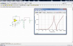
Fyi, the simulated output impedance response of the buffer configuration in fig3003, with OPA1611.
😱
Well if the plan fails see the attached backup plan that is ready (to order), just in case. Right now my measurements show exactly the same 2nd harmonic as my SB0490 loopback. (Meaning I am measurement ADC limited.) So if the changes make anywhere near the claimed improvements then I really should be ok with it.
Attachments
Last edited:
if one wants the very best, IMO, he would have at least to try the CEN/SEN I/V or pass d1 style I/V, which are thankfully not too expensive to build. i have tried both in the past and they blew my mind.
that said, In my topping d10s, i have the opa1656 doing the I/V and then LME 49720 for single-end conversion. It is the same topology as «Ian opamp output stage for sabre dacs» .
I am currently playing with supplies, i can say the combo is capable of quite fine detail and dynamics, and all that only playing with main supply and AVCC supply. I didn't expect that kind of sound at all from a so cheap device. That means «cheap» xmos u208, es9038q2m in asynchronous and it's output analog stage as is, are very capable parts, at least i would think for a lot of audiophiles... quite rejoicing to see !
i'll post subjective impressions upon further enhancement.
Last edited:
Fyi, the simulated output impedance response of the buffer configuration in fig3003, with OPA1611.
Doesn't the load look largely like a few hundred ohm resistor to ground?
Last edited:
I guess its okay to say that there are better AVCC regulator designs than opamp buffers, but well designed buffers can be very good. In any case, its not just choice of opamp that matters. Layout, passive component choices, etc., can make a potentially good design turn out bad. Unfortunately, those same things can't make a bad design turn out good 🙂
Doesn't the load look largely like a few hundred ohm resistor to ground?
I wonder if anyone has a back of the envelope guess-estimate of the DAC load? Two sets of 64 switches??? I thought someone said 50kOhm each for an older ESS chip? Maybe 50kOhm/(2*64)=390 Ohms?
Is the total 6mA for both AVCC_R/L or each? (Page 50 of datasheet.) I think they mean total.
3.3V/0.003mA = 1100 Ohms.
3.3V/0.006mA = 550 Ohms.
Note that I don't know and I don't claim to know. I am just curious/discussing it in case someone else knows. So no
please.The trick with opamp buffers is that the cap on the output will resonate with the opamp 'virtual output inductance' - - as it is shown in the sim.
The trick is to push down this resonance frequency.
John Westlake (an the M-dac..) had used 1000uF capacitance for this reason.
The trick is to push down this resonance frequency.
John Westlake (an the M-dac..) had used 1000uF capacitance for this reason.
Another option to tinker on is a RC filter after a chosen regulator to further reduce noise and isolate the influence of the regulator. It is not of course a textbook approach and not refined, but in my experience it gives a further subjectively very natural character to the sound. Especially with a good cap like say Nichicon KZ 1mF. The impression of dynamics will suffer a little, but i think many could like the overall result. I think the cheap ebay board most talked about has that already, doesn't it?
if anything, i think it is useful reference to evaluate a proper audio regulator.
if anything, i think it is useful reference to evaluate a proper audio regulator.
Last edited:
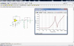
Here it is with 200ohm to ground
How does it look for the other output cap option? (The electrolytic cap?) My board come stock with an Elna 100uF 16V RA3 at AVCC_R/L. So if you go up to 0.6 Ohm for the model what do you see?
Perhaps you can vary it and see what looks like a safe range.
Here it is with 200ohm to ground
One choice might be to choose a cap that is very lossy by 100kHz or so. Electrolytics can be rather nonlinear in that respect. My capacitance meter has trouble reading a value for some electrolytics starting as low as 10kHz. Passive component choices can make a lot of difference in final results. Experimentation is not necessarily a bad thing in some cases where models are lacking.
Last edited:
The trick with opamp buffers is that the cap on the output will resonate with the opamp 'virtual output inductance' - - as it is shown in the sim.
The trick is to push down this resonance frequency.
John Westlake (an the M-dac..) had used 1000uF capacitance for this reason.
So maybe two parallel 560uF Panasonic OS-CON? (Sorry I could not resist... A bit of a private joke. Mine measure 3mOhm while the datasheet says 7mOhm max.)
One choice might be to choose a cap that is very lossy by 100kHz or so. Electrolytics can be rather nonlinear in that respect. My capacitance meter has trouble reading a value for some starting as low as 10kHz. Passive component choice can make a lot of difference in final results. Experimentation is not necessarily a bad thing in some cases where models are lacking.
With some experimenting your 2nd harmonic might start out at -69 dBc and end up at -104 dBc pretty quickly 🙂
Let's make it clear, what is simulated is that '22uF film cap ' on the output, as option F in the schematic.
Which is ~the absolute worst scenario.
All other things, higher value, more lossy electros, are obviosly better, less resonant, but it does not "go away" until one arrives at 1mF zone.
Many tricks can be tried, like a second, parallel small elko, with some ohm ESR, which exerts a 'snubbing' effect on the created resonance.
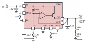
But. Why not just apply an LT3042, without complications and to good effect..
(The higher cap values are obviously slowing down the opamp response time.. out goes the fast response, that is slow and long resonaces could appear.
An LT3042 is having the fastest and best, no resonance response with exactly that, a 10uF/20uF film cap on the output..)
Which is ~the absolute worst scenario.
All other things, higher value, more lossy electros, are obviosly better, less resonant, but it does not "go away" until one arrives at 1mF zone.
Many tricks can be tried, like a second, parallel small elko, with some ohm ESR, which exerts a 'snubbing' effect on the created resonance.
But. Why not just apply an LT3042, without complications and to good effect..
(The higher cap values are obviously slowing down the opamp response time.. out goes the fast response, that is slow and long resonaces could appear.
An LT3042 is having the fastest and best, no resonance response with exactly that, a 10uF/20uF film cap on the output..)
Last edited:
Why not LT3042? In my case I want to enjoy some DIY with the parts that I have (first). I will see what I can achieve. After that I might buy the $16 worth of LT3042 (three of them for the board).
Until then I wonder what happens in your simulation if you wire an LM4562 as shown in the attached image where the reference (3.3V) goes to the inverting input and you use a 2N4403 as the PNP shown in the LT3042?
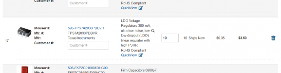
And I will definitely consider the $0.35 TPS7A2033PDBVR before the $5.60 LT3042. I actually get a tiny bit offended when a company charges the DIY community obscenely more than they charge their main customers.
Until then I wonder what happens in your simulation if you wire an LM4562 as shown in the attached image where the reference (3.3V) goes to the inverting input and you use a 2N4403 as the PNP shown in the LT3042?
And I will definitely consider the $0.35 TPS7A2033PDBVR before the $5.60 LT3042. I actually get a tiny bit offended when a company charges the DIY community obscenely more than they charge their main customers.
Attachments
Last edited:
I can try that - and for sure will have to play with the configuration, compensation, optimisation.
And if we are into it, why not try Pavel circuit, as quoted by Eziitis... which had passed many phases already?
https://www.diyaudio.com/forums/digital-line-level/314935-es9038q2m-board-663.html#post6502009
And if we are into it, why not try Pavel circuit, as quoted by Eziitis... which had passed many phases already?
https://www.diyaudio.com/forums/digital-line-level/314935-es9038q2m-board-663.html#post6502009
I could look at Pavel's circuit. (But the LTC6228 is $4 each.)
Again I would like to see what I can do with the NE5532, NJM4580 and LM4562 in my parts box first before I order more new stuff.
Do you know if anyone has built Pavel's circuit with a common op-amp?
Again I would like to see what I can do with the NE5532, NJM4580 and LM4562 in my parts box first before I order more new stuff.
Do you know if anyone has built Pavel's circuit with a common op-amp?
Last edited:
- Home
- Source & Line
- Digital Line Level
- ES9038Q2M Board