^^^
You'd be much comfortable with Markw4 and his posse advice, they will not quibble over inconsistent measurements results. I'm out for the time being.
Which post and measurement are you referring to (the high noise result)? Is it one of the noisy scope measurements or a spectrum measurement?
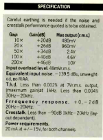
I have attached the reasoning behind the input transistor and specs from the original Douglas Self design that the LNA was based upon. (The actual LNA has some improved parts (such as the op amps, power supplies, capacitors, etc.)) There are other changes such as 60 dB max gain.
I tried to use the same reasoning for the transistors in the shunt regulator and then the following clean up capacitance multiplier.
Attachments

Nichicon UES appears to be a bipolar electrolytic type. At some frequency it will probably look more like an inductor than a capacitor. Larger case sizes and uF values may turn inductive at lower frequencies. Suggest you might try a more suitable capacitor for RF use.
Perhaps you have an RF generator you can use to check the frequency response of the test setup, ideally up to and above the dac clock frequency? If not, perhaps good to try the scope without the low noise preamp to see if there is wideband consistency between readings with and without the added gain stage. What is the scope bandwidth specification?
EDIT: Completely agree 0.5nV/rtHz is not credible. Something has to be wrong somewhere, maybe more than one thing.
EDIT2: Your FFT display shows you are using exponential averaging. You understand that the processing averages out displayed noise?
EDIT3: That a soundcard scope program you are using?
I am using REW (V5.20, I think it is a beta version.). What sort of averaging do you suggest in REW?
I don't have a fast scope. For the sound card I am currently using 44.1kHz and the scope itself is very slow only 1Msps.
For the sound card frequency range I believe the Nichicon UES behavior is very good? It is specific for audio use.
I would only add that AC coupling a LNA to a DC source requires to wait enough time so that any displacement current through the cap is low enough to not interfere with the measurement. Depending on the cap value (here, unknown) and the LNA input impedance (here, unknown) this can extend even minutes. Capacitor leakages can completely falsify measurement results, that's why a LNA with high input impedance and a film capacitor are recommended.
Last edited:
Kozard,
I have to largely agree with syn08. Your noise graphs look suspicious. And without schematics of you regulators it is virtually impossible to analyse your results. Anyhow I suggest you "calibrate" you LNA/REW by shorting the LNA input with resistors of varying resistance (e.g. 100ohm and 1kohm). You should see straight noise line corresponding to the thermal noise of the resistor. 100ohm is about 1.3nV/√Hz, 1kohm is about 4nV/√Hz.
And as syn08 pointed out your approach seems to be well inline with the thread.
I will try the 100Ohm and 1kOhm and again look for any mistakes.
^^^
I'm afraid you keep shooting in all targets and running around in circles. This makes helping you very difficult. If you want to believe that a DC regulator can achieve 0.5nV/rtHz noise, that a discrete regulator can necessary exceed specialized IC performance metrics, that all your measurements are flawless, and you can choose at any moment one at your convenience, for reference, etc... then I'm afraid you are beyond my help abilities.
You'd be much comfortable with Markw4 and his posse advice, they will not quibble over inconsistent measurements results. I'm out for the time being.
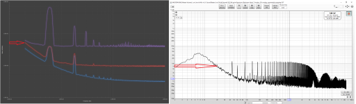
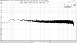
In the attached image I have your data on the left and my data on the right. My noise level is clearly higher. So why are you saying my noise is 0.5nV/rtHz noise? Is there any chance that perhaps you read the graph wrong?
The red arrow on your data corresponds to 5nV/rtHz on your Y-Axis and the red arrow on my data corresponds to 7nV/rtHz on my Y-Axis.
What am I not understanding? I thought your noise levels were:
For your reference, the VREF noise (LTC6655 plus LT3045) for my instrumentation ADC project is slightly over 5nV/rtHz and the AVDD noise (LT3045) is around 7nV/rtHz. These are about 50 times less than what you currently get at the 7805 output.
If I understand your post you have noise levels that are ten times 0.5nV/rtHz and my measurement looks like higher noise than yours.
Attachments
Last edited:
For measuring noise with an FFT, and if you are using the noise information calculated by REW, you need to know if the calculation is done based on the averaged data. If so, then at best only spurs will be calibrated, not noise. If you want to measure noise, you can't first filter it out by averaging. You could try turning off FFT averaging in REW and see if the displayed noise numbers change as a result. If so, then you should turn off averaging for noise measurements.
To be clear, I don't know much about REW, and I don't know what the problem is with your measurements at this point. Its just that we know something has to be wrong, so start checking things you can check. Often that leads to a fix much faster than a fully analytical approach. If the easy way doesn't work, okay. One can always dig deeper.
To be clear, I don't know much about REW, and I don't know what the problem is with your measurements at this point. Its just that we know something has to be wrong, so start checking things you can check. Often that leads to a fix much faster than a fully analytical approach. If the easy way doesn't work, okay. One can always dig deeper.
Markw4; said:For measuring noise with an FFT, and if you are using the noise information calculated by REW, you need to know if the calculation is done based on the averaged data. If so, then at best only spurs will be calibrated, not noise. If you want to measure noise, you can't first filter it out by averaging. You could try turning off FFT averaging in REW and see if the displayed noise numbers change as a result. If so, then you should turn off averaging for noise measurements.
To be clear, I don't know much about REW, and I don't know what the problem is with your measurements at this point. Its just that we know something has to be wrong, so start checking things you can check. Often that leads to a fix much faster than a fully analytical approach. If the easy way doesn't work, okay. One can always dig deeper.
Can you please examine the side by side graphs in post 6825? There is something I don't understand. As far as I can tell syn08 is quoting 5nV/rtHz and 7nV/rtHz for his case and my measurement graph (spectrum) is clearly higher than his. [His posts 6791 and 6796.] So when he looks at my data and says that it is 0.5nV/rtHz is he making a mistake and misreading my graph?
As far as REW goes the levels don't change as the averages get added up after each FFT except that the noise in the graph reduces. I think bohrok2610 uses REW so perhaps he can comment on whether it is wrong to use exponential averages? I don't think it is. But if that is wrong I can change that.
Measuring 100Ohm and 1000Ohm resistors is really easy so I can check that quickly.
So why are you saying my noise is 0.5nV/rtHz noise?
What am I not understanding?
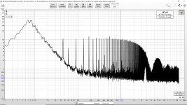
Your graph has lots of hash but inbetween those spikes the noise floor seems to be at 0.5nV/√Hz which is highly suspicious. Another suspicious thing is that the hashes are not related to mains frequency (e.g. one at 45Hz).
As far as REW goes the levels don't change as the averages get added up after each FFT except that the noise in the graph reduces. I think bohrok2610 uses REW so perhaps he can comment on whether it is wrong to use exponential averages? I don't think it is. But if that is wrong I can change that.
You can use averages for noise measurements. Without averaging the graphs would be virtually unreadable.
https://www.edn.com/simple-circuits-reduce-regulator-noise-floor/
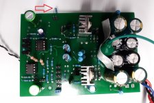
The last stage is a capacitance multiplier for "cleanup" after the shunt regulator. The shunt regulator charges a large low ESR capacitor which is followed by the capacitance multiplier. The capacitance multiplier uses three parallel large die/low base resistance die and the output of that capacitance multiplier charges a large very low ESR capacitor too (1000uF).
Is it possible that the low noise floor at 1kHz is due to the use of the very large low ESR bypass capacitors? Especially the last one on the output?
Edit: I followed the shunt regulator with a capacitance multiplier after reading the article: https://www.edn.com/simple-circuits-reduce-regulator-noise-floor/
There a simple LM317 followed by a capacitance multiplier was approaching the TPS7A4700 (see figure 9 in the link). My objective is that my shunt regulator would be lower noise than the LM317 and that my capacitance multiplier would be lower noise than the one in that article.
Anyways I will measure some resistors and see where that leads.
Your graph has lots of hash but inbetween those spikes the noise floor seems to be at 0.5nV/√Hz which is highly suspicious. Another suspicious thing is that the hashes are not related to mains frequency (e.g. one at 45Hz).
The last stage is a capacitance multiplier for "cleanup" after the shunt regulator. The shunt regulator charges a large low ESR capacitor which is followed by the capacitance multiplier. The capacitance multiplier uses three parallel large die/low base resistance die and the output of that capacitance multiplier charges a large very low ESR capacitor too (1000uF).
Is it possible that the low noise floor at 1kHz is due to the use of the very large low ESR bypass capacitors? Especially the last one on the output?
Edit: I followed the shunt regulator with a capacitance multiplier after reading the article: https://www.edn.com/simple-circuits-reduce-regulator-noise-floor/
There a simple LM317 followed by a capacitance multiplier was approaching the TPS7A4700 (see figure 9 in the link). My objective is that my shunt regulator would be lower noise than the LM317 and that my capacitance multiplier would be lower noise than the one in that article.
Anyways I will measure some resistors and see where that leads.
Last edited:
Kozard,
You start with the actual noise in the circuit you want to measure. If you use an LNA then you will add the noise of the LNA and you will multiply the noise of the DUT by the gain of the amplifier. If you then have a calibrated FFT, you can work backwards from that to infer the noise of your DUT.
The thing about directly reading noise level from an otherwise calibrated FFT graph display is that the FFT bin size should be 1Hz and no averaging used. (You can correct displayed graph noise level for other bin sizes using calculations.) I would guess that displayed noise numbers in REW are corrected for bin size (you know, the little box in the upper corner that gives you some noise numbers), but I don't know if they are calculated after averaging.
^^^
I'm tired repeating this: averaging doesn't affect the noise level, it only shows a pretty/sharper picture so that you don't have to interpolate through the "grass".
As of the bin size, as long as the noise is plotted in V/rtHz this is automatically included.
I'm tired repeating this: averaging doesn't affect the noise level, it only shows a pretty/sharper picture so that you don't have to interpolate through the "grass".
As of the bin size, as long as the noise is plotted in V/rtHz this is automatically included.
Another non trivial fact: electrolytic capacitors have noise, and the larger the value, the larger the noise. That is because they have a leakage current, the larger the cap the larger the leakage, and physics is telling us that any flowing current is associated with a noise source, following Inoise=SQRT(2*q*I) [A/rtHz]. So relying blindly on cap multipliers is not necessary a great solution to lower the noise, since the series transistor multiplies both the capacitor and its noise (the electrolytic noise current above is injected in the transistor base, so Beta (the transistor current gain) applies. That aparently simple cap multiplier needs some careful design, which obviously did not happen here.
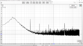
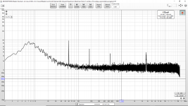
Attached in order is:
- LNA Shorted.
- 100 Ohm Resistor (Soldered to LNA input.)
- 1000 Ohm Resistor (Soldered to LNA input.)
- Output of preregulator. The 45Hz seems to come from the preregulator so I will need to find out what is wrong.
Attachments
Last edited:

Kozard,
I have to largely agree with syn08. Your noise graphs look suspicious. And without schematics of you regulators it is virtually impossible to analyse your results. Anyhow I suggest you "calibrate" you LNA/REW by shorting the LNA input with resistors of varying resistance (e.g. 100ohm and 1kohm). You should see straight noise line corresponding to the thermal noise of the resistor. 100ohm is about 1.3nV/√Hz, 1kohm is about 4nV/√Hz.
And as syn08 pointed out your approach seems to be well inline with the thread.
My resistor measurements seem to agree very well with the 1.3nV/√Hz for 100Ohm and 4nV/√Hz for 1000Ohm.
The LNA is basically the Wireless World Douglas Self MC LNA with improved components (such as op amps) that are now available. [And some adjustments for measurement usage instead of MC preamp.] It should not be surprising that it works.
Last edited:
Does any kind soul have an LT Spice simulation of some sort of regulator or reference with the simulation nicely and properly setup to simulate noise? If they do I would greatly appreciate it if you could share it. If it were some sort of discrete regulator that would be nice too.
Last edited:
Another non trivial fact: electrolytic capacitors have noise, and the larger the value, the larger the noise. That is because they have a leakage current, the larger the cap the larger the leakage, and physics is telling us that any flowing current is associated with a noise source, following Inoise=SQRT(2*q*I) [A/rtHz]. So relying blindly on cap multipliers is not necessary a great solution to lower the noise, since the series transistor multiplies both the capacitor and its noise (the electrolytic noise current above is injected in the transistor base, so Beta (the transistor current gain) applies. That aparently simple cap multiplier needs some careful design, which obviously did not happen here.
At the following link you can see a simple LM317 + capacitance multiplier approaching the performance of the low noise Ti TPS7A4700. See figure 9. So I don't think it is crazy at all to think that something better than the LM317 followed by a better capacitance multiplier might be low enough noise for this hobby DAC...
Again, figure 9:
https://www.edn.com/simple-circuits-reduce-regulator-noise-floor/
And yes, I will be measuring various configurations both before and after the cap multiplier and with a variety of different cap types and sizes.
Relax everybody. Today was just the very first prototype put together for a hobby project while enjoying my morning coffee... Sigh... And no, I don't know what the 45Hz is.
And this is just the preregulator. It will be followed by the LM4562 as per post 3003. The LM4562 PSRR can easily reject a low frequency noise hump. I have not decided on film versus electrolytic let alone which manufacturer or series...
Last edited:
...averaging doesn't affect the noise level...
My bad. I was thinking of a different type of processing, not simple averaging.
At the following link you can see a simple LM317 + capacitance multiplier approaching the performance of the low noise Ti TPS7A4700. See figure 9. So I don't think it is crazy at all to think that something better than the LM317 followed by a better capacitance multiplier might be low enough noise for this hobby DAC...
Again, figure 9:
https://www.edn.com/simple-circuits-reduce-regulator-noise-floor/
And yes, I will be measuring various configurations both before and after the cap multiplier and with a variety of different cap types and sizes.
Relax everybody. Today was just the very first prototype put together for a hobby project while enjoying my morning coffee... Sigh... And no, I don't know what the 45Hz is.
And this is just the preregulator. It will be followed by the LM4562 as per post 3003. The LM4562 PSRR can easily reject a low frequency noise hump. I have not decided on film versus electrolytic let alone which manufacturer or series...
We must be living in parallel universes, I don't see that in fig. 9. What I see is a comparison between:
- A bad LM317 design
- A good LM317 design (bypassed properly)
- A passive RC filter
- A passive LC filter
- The TPS7A4700 noise
- His measurement tool noise floor.
Now, can you read the noise levels on the Y axis in fig.9? I read the TPS7A4700 having 20nV/rtHz @ 10KHz, which is what I would expect. His measurement setup has between 5 and 6nV/rtHz.
Your measurements are showing a noise of 0.5nV/rtHz both for the LNA with shorted input (first plot in #6834) and at the preregulator output (last plot in #6834), so the power supply noise and the LNA noise floor are the same. The only difference is the amount of hash of unknown origin on the preregulator noise plot.
Your results make absolutely no sense, that's what everybody is trying to convey, while you keep ignoring advice and keep truckin'. Good luck.
P.S. If I would be forced to place a bet, I would put my money on the input electrolytic in your LNA having enough leakage (at the pre-regulator output voltage) to saturate the LNA input stage and make its gain virtually zero dB. Hence the illusion your pre-regulator output noise is virtually zero.
Last edited:
- Home
- Source & Line
- Digital Line Level
- ES9038Q2M Board