My resistor measurements seem to agree very well with the 1.3nV/√Hz for 100Ohm and 4nV/√Hz for 1000Ohm.
Yes, at least that is now sorted.
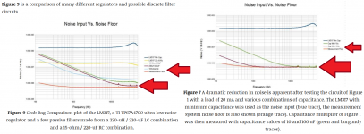
We must be living in parallel universes, I don't see that in fig. 9. What I see is a comparison between:
- A bad LM317 design
- A good LM317 design (bypassed properly)
- A passive RC filter
- A passive LC filter
- The TPS7A4700 noise
- His measurement tool noise floor.
Now, can you read the noise levels on the Y axis in fig.9? I read the TPS7A4700 having 20nV/rtHz @ 10KHz, which is what I would expect. His measurement setup has between 5 and 6nV/rtHz.
Your measurements are showing a noise of 0.5nV/rtHz both for the LNA with shorted input (first plot in #6834) and at the preregulator output (last plot in #6834), so the power supply noise and the LNA noise floor are the same. The only difference is the amount of hash of unknown origin on the preregulator noise plot.
Your results make absolutely no sense, that's what everybody is trying to convey, while you keep ignoring advice and keep truckin'. Good luck.
P.S. If I would be forced to place a bet, I would put my money on the input electrolytic in your LNA having enough leakage (at the pre-regulator output voltage) to saturate the LNA input stage and make its gain virtually zero dB. Hence the illusion your pre-regulator output noise is virtually zero.
I have put the TPS7A4700 graph (in figure 9) next to the LM317 + cap multiplier (in figure 7) together in the attached image to make it more clear. If you read the article and look at the graphs isn't the LM317 + 100u cap multiplier lower noise than TPS7A4700? A lot lower noise? [Hits the noise floor of the measurement?] So if I do that with a shunt regulator that is already much lower noise than the LM317 do we have a chance at even lower noise?
I don't have huge film capacitors but I can try using the biggest crossover film capacitor I have to test out the leakage theory with the LNA. Why would a 50V Nichicon UES series have that much leakage?
Would the cap multiplier reduce the noise at higher frequencies? Would leakage in the cap multiplier capacitor increase noise at lower frequencies? I can try different capacitors types and sizes tomorrow and I can probe with the capacitor multiplier removed and with only films caps in the capacitor multiplier for low leakage.
Attachments
Last edited:
Your results make absolutely no sense, that's what everybody is trying to convey, while you keep ignoring advice and keep truckin'.
How is it ignoring advice when I have made every diagnostic measurement suggested by three different people? Voltage waveforms, then using a scope for voltage waveforms at higher frequencies/bandwidth, solder the LNA cable shorted on the DAC board, measure 100Ohm and 1000Ohm resistors, etc.
And how is stopping to repeat measurements and suggested diagnostics anything like "keep truckin'"?
How is that ignoring advice? And what was found to be wrong? Nothing really so far? There was a bad HPRO power supply. LNA verified with 100 Ohm and 1000 Ohm. [Those results make perfect sense. And the LNA measured with the input shorted, don't those results also make perfect sense with the sections of the Wireless World/Douglas Self article that I posted?] Maybe tomorrow I find out that I need a different capacitor type at the input of the LNA. Is that the end of the world? Is that a mortal sin? If it needs to be a different type due to leakage I will fix it and remeasure. All nice and calmly while enjoying my coffee.
And what is wrong with taking published circuits (ESP mic preamp shunt regulator, Douglas Self LNA, EDN cap multiplier) and putting them together? And using what Douglas Self did in the LNA (3x parallel 2N4403) and applying that to the ESP mic preamp shunt regulator and the EDN cap multiplier article to reduce noise? Along with the published work I found on Zener and LED noise?
If there is something wrong with the circuit or the LNA it will eventually be found. The first day trying to make and measure a low noise preregulator is no cause for going bananas. Relax. We all don't need to buy the most expensive LT or Ti chips. Some of us will enjoy building something of their own making. I think they call it something like DIY. If my little preregulator project fails then I will click "buy" next to the Ti or LT chip at my favorite distributor and not worry about it.
Last edited:
I have put the TPS7A4700 graph (in figure 9) next to the LM317 + cap multiplier (in figure 7) together in the attached image to make it more clear.
That's part of the problem. You refer fig.9, then add fig.7 for an unwarranted comparison (what's the point of comparing a cap multiplier noise with a voltage regulator noise?) then you make the unwarranted assumption that if a cap multiplier noise is low, whatever noisy stuff you add in front will not go through, then you make the unwarranted assumption that a regulator + cap multiplier is a better power supply for a DAC (when in fact the output impedance and its frequency dependence will be as poor as it gets), etc...
Regarding not listening to advice, you were told several times "don't touch anything else" now you are showing again the LNA with the input short and resistors soldered at the LNA board, instead on keeping the cable in the same position, grounded to the DUT. And then you keep wondering where the measurements crud is coming from. And the show continues... Who do you think has the time and patience to spoon feed you and follow on every step? That's not me, life is to short.
If you need help, accept you are a beginner that needs coaching, start with stating your objectives, post the schematics for every tool and DUT you are using, read carefully and try to understand the literature (ask for help when in doubt), show how you plan to interconnect the parts, ask what would be the best way to evaluate the results, listen to suggestions, keep track of what you are doing, interpret and cross check the results (or ask for help to do so), etc...
And all these would be much better in separate forum threads (like one in the Power Supplies section "Low noise power supplies"), then move to the DAC integration step in another thread, etc... Step by step, a one size fits all approach is not useful - there is no shortcut in the journey of learning.
syn08; said:That's part of the problem. You refer fig.9, then add fig.7 for an unwarranted comparison (what's the point of comparing a cap multiplier noise with a voltage regulator noise?) then you make the unwarranted assumption that if a cap multiplier noise is low, whatever noisy stuff you add in front will not go through, then you make the unwarranted assumption that a regulator + cap multiplier is a better power supply for a DAC (when in fact the output impedance and its frequency dependence will be as poor as it gets), etc...
Slow down and read the article carefully. Right under figure 7 it says (exact quote):
So yes, it does reduce the LM317 noisy stuff that was put in front of the cap multiplier. So it is a completely warranted comparison. I guess you just don't get it. Reading comprehension.Figure 7 is a comparison of the performance of the capacitance multiplier of Figure 1 and the LM317 used as a noise source. The capacitance multiplier can be seen to work well in reducing the noise from the LM317 regulator rather dramatically.
And apparently you forgot again that this is the preregulator for the LM4562 which will supply the AVCC_R/L. Never mind. You don't need to ramble on about output impedance now. More rubbish. The LM4562 output impedance is just fine. I don't need or want your "advice".
And why go on about measurement crud? It is a noisy USB SB0490 and the 60Hz and harmonics are quite clear in your measurement too!
Last edited:
I don't need or want your "advice".
Perfect, good luck!
P.S. Except that you have crud at multiples of 45Hz too.
Last edited:
Regarding not listening to advice, you were told several times "don't touch anything else" now you are showing again the LNA with the input short and resistors soldered at the LNA board, instead on keeping the cable in the same position, grounded to the DUT. And then you keep wondering where the measurements crud is coming from.
You do realize that when someone asked me to measure 100 Ohm and 1000 Ohm there was no DUT except that resistor, right??? The short and the DUT (resistor) were in exactly the same place... Never mind... No cable involved at all.
Last edited:
Perfect, good luck!
P.S. Except that you have crud at multiples of 45Hz too.
Why call that crud? It is not coming from the LNA. Or the DUT or cables when the DUT is powered off. Is that useful information about something that needs to be improved in the DUT?
P.S. So when you are wrong about the EDN article you just jump to "you have crud at 45Hz?" And rubbish about output impedance?
Last edited:
By the way, a solution to the electrolytic leakage problem can be found on pages 897 and 898 of "The Art of Electronics" Third Edition. It is called the "bootstrap cure".
It is in Figure 13.19 between the ADR445B reference and the AD8676.
It is in Figure 13.19 between the ADR445B reference and the AD8676.
Hopefully things will calm down a little and we can get back to having some fun with dacs, and maybe a bit of other stuff.
BTW, there are reasons capacitance multipliers are sometimes favored for audio. The short explanation is that some low PSRR loads can interact with their power supply in a way that tends to be favorable for human perceptual enjoyment. And, the effect can be measured. Will leave further discussion for some later time.
BTW, there are reasons capacitance multipliers are sometimes favored for audio. The short explanation is that some low PSRR loads can interact with their power supply in a way that tends to be favorable for human perceptual enjoyment. And, the effect can be measured. Will leave further discussion for some later time.
Last edited:
Due to the technically incorrect information being posted yesterday I decided to replicate the published results shown in the EDN article "Simple circuits reduce regulator noise floor".
The link to the article is here: https://www.edn.com/simple-circuits-reduce-regulator-noise-floor/
My results (attached) agree well with the published results. So it is no longer possible (in my opinion) to continue posting technically incorrect information about the noise floor reductions possible with a capacitance multiplier.
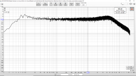
First I recreated the LM317 regulator shown in Figure 4 of that link. In Figure 7 of that link the LM317 is used without a bypass on the ADJ terminal deliberately to create a high amount of noise. That is the top (blue) trace in Figure 7 of that link and shows about 1.5uV/√Hz. In my first attachment I measured about 1.1uV/√Hz with my duplicate using the information and schematic in the article. That is pretty reasonable agreement considering I don't know much about his construction methods, equipment, etc.
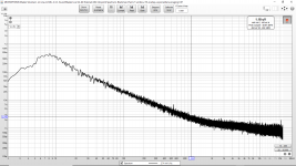
Next I added the capacitance multiplier of Figure 1 (in the above linked article) after the LM317. That was to recreate the red trace in Figure 7 of that link where the author showed about 6nV/√Hz at 1kHz. In my second attachment I measured about 2.5nV/√Hz (at 1kHz to compare to the linked article) with my duplicate using the information and schematics in the article. I am not sure if the agreement would be better if I knew the manufacturers, part numbers and series for the capacitor he used or the brand of LM317. (Or other details of the construction, etc.) But it is close enough agreement.
Here is a crucial quote (direct quote) from the linked EDN article:
Next I improved the noise even further using techniques that can be read about in books like The Art of Electronics or Wireless World articles like the Douglas Self MC Preamp (the basis of my LNA).
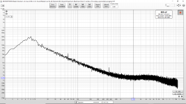
In attachment 3 I made the capacitance multiplier lower noise by switching from 1000 Ohms to 100 Ohms, from 100uF to 2200uF and by paralleling four 2N4401. (The EDN author used 1000 Ohms, 100uF and one 2N4401 in the capacitance multiplier of Figure 1 in the linked article.)
Next I added the LM317 ADJ terminal bypass capacitor that the EDN author deliberately omitted (to create a high noise output from the LM317.) That is my attachment 4 and shows a dramatic reduction in the noise in agreement with my other work.
So I believe by duplicating the linked published work of another independent author I have thoroughly disproved the technically incorrect information that was posted yesterday. I think it is reasonable to ask people who don't know what they are talking about to please stop posting technically incorrect information and also to please stop disparaging the work of others that they do not understand.
Also please note that the suggestion posted yesterday about input capacitor leakage saturating the LNA input is also wrong. The Nichicon UES capacitor works perfectly well here and does not need to be replaced with a film capacitor.
Next I believe these experiments and measurements (included the linked article) show that the leakage current and associated noise of the electrolytic capacitor in the capacitance multiplier does not appear to be a significant contributor in these circuits.
Also the prior suggestion that discrete circuits and special techniques can not exceed specialized circuits such as TPS7A4700 is also false. There are advantages of a monolithic IC. There are also disadvantages such as small transistors higher base resistance, much smaller capacitors, etc.
Finally the only way I found to reduce the 45 Hz spurs was to add another shielding tin. This time the DUT is in the added shielding tin and the two tins are isolated. (The LNA tin and the DUT tin.) The connection between the two tins is now twisted pair.
The link to the article is here: https://www.edn.com/simple-circuits-reduce-regulator-noise-floor/
My results (attached) agree well with the published results. So it is no longer possible (in my opinion) to continue posting technically incorrect information about the noise floor reductions possible with a capacitance multiplier.
First I recreated the LM317 regulator shown in Figure 4 of that link. In Figure 7 of that link the LM317 is used without a bypass on the ADJ terminal deliberately to create a high amount of noise. That is the top (blue) trace in Figure 7 of that link and shows about 1.5uV/√Hz. In my first attachment I measured about 1.1uV/√Hz with my duplicate using the information and schematic in the article. That is pretty reasonable agreement considering I don't know much about his construction methods, equipment, etc.
Next I added the capacitance multiplier of Figure 1 (in the above linked article) after the LM317. That was to recreate the red trace in Figure 7 of that link where the author showed about 6nV/√Hz at 1kHz. In my second attachment I measured about 2.5nV/√Hz (at 1kHz to compare to the linked article) with my duplicate using the information and schematics in the article. I am not sure if the agreement would be better if I knew the manufacturers, part numbers and series for the capacitor he used or the brand of LM317. (Or other details of the construction, etc.) But it is close enough agreement.
Here is a crucial quote (direct quote) from the linked EDN article:
It is also crucial to understand Figures 7 & 9 of the linked article together along with the text of the article. It shows that the noisy LM317 (even without ADJ bypass) and the very simple capacitance multiplier (when used together as in the linked article) has a much lower noise floor than the expensive and specialized TPS7A4700. That is published in the linked EDN article and I just recreated the data.Figure 7 is a comparison of the performance of the capacitance multiplier of Figure 1 and the LM317 used as a noise source. The capacitance multiplier can be seen to work well in reducing the noise from the LM317 regulator rather dramatically.
Next I improved the noise even further using techniques that can be read about in books like The Art of Electronics or Wireless World articles like the Douglas Self MC Preamp (the basis of my LNA).
In attachment 3 I made the capacitance multiplier lower noise by switching from 1000 Ohms to 100 Ohms, from 100uF to 2200uF and by paralleling four 2N4401. (The EDN author used 1000 Ohms, 100uF and one 2N4401 in the capacitance multiplier of Figure 1 in the linked article.)
Next I added the LM317 ADJ terminal bypass capacitor that the EDN author deliberately omitted (to create a high noise output from the LM317.) That is my attachment 4 and shows a dramatic reduction in the noise in agreement with my other work.
So I believe by duplicating the linked published work of another independent author I have thoroughly disproved the technically incorrect information that was posted yesterday. I think it is reasonable to ask people who don't know what they are talking about to please stop posting technically incorrect information and also to please stop disparaging the work of others that they do not understand.
Also please note that the suggestion posted yesterday about input capacitor leakage saturating the LNA input is also wrong. The Nichicon UES capacitor works perfectly well here and does not need to be replaced with a film capacitor.
Next I believe these experiments and measurements (included the linked article) show that the leakage current and associated noise of the electrolytic capacitor in the capacitance multiplier does not appear to be a significant contributor in these circuits.
Also the prior suggestion that discrete circuits and special techniques can not exceed specialized circuits such as TPS7A4700 is also false. There are advantages of a monolithic IC. There are also disadvantages such as small transistors higher base resistance, much smaller capacitors, etc.
Finally the only way I found to reduce the 45 Hz spurs was to add another shielding tin. This time the DUT is in the added shielding tin and the two tins are isolated. (The LNA tin and the DUT tin.) The connection between the two tins is now twisted pair.
Attachments

Last edited:
I guess some people use DAC as effect box. There is a simpler way, it's called equalizer and many use it including professionals.The short explanation is that some low PSRR loads can interact with their power supply in a way that tends to be favorable for human perceptual enjoyment. And, the effect can be measured.
So you were talking about amplifier power supply when you mentioned "some low PSRR loads can interact with their power supply"?
Kozard,
The difference between a Texas TPxxx chip regulator and your cap multiplier is that the TI chip is not only low noise but also mohm output impedance & MHz bandwith.
While the cap multiplier is ohm (10ohm? Depends on current) output impedance. That means ~no load regulation.
The LT3042 is 2nV/sqrtHz, and ~5mohm up to 1MHz, at least. That is ~1000 times better load regulation than a cap multiplier.
You have started to measure on the dac reference pin, this difference should show up, if You re-apply that cap multiplier..
Ciao, George
In case you missed it the DAC reference pin is supplied by the LM4562, not the cap multiplier.
See the LM4562 or LME49720NA in the post 3003 schematic. (Page 301 of the thread.) My plan is for the LM4562 and the filter to be located under the board (attached to the ground plane next to the AVCC_R/L pins for that dual op-amp). For the less critical pins I might just use NE5532 (NJM5532DD) until I get more LM4562 and/or decide they are really necessary for the other pins.
That part of the mod (LM4562 or LME49720NA) originates from an ESS recommendation. I am probably not going to try the AD797.
If ESS believes this has sufficient bandwidth and sufficiently low output impedance I am not going to argue with them. If the manufacturer recommends it, several peers verify it, my measurements are ok and if I like the sound then that is good enough for me.
Last edited:
kozard,
OPA1612 is an opamp ESS apparently didn't try at the time they created the document you refer to, but its what they use now on their evaluation boards. IME its it better part for dacs than LME49720, at least for the opamps directly connected to the dac chip. Subsequent processing stages might be a better place to try LME49720. If you want to try to stick with 49720 because its cheaper, maybe that would be a sensible reason.
OPA1612 is an opamp ESS apparently didn't try at the time they created the document you refer to, but its what they use now on their evaluation boards. IME its it better part for dacs than LME49720, at least for the opamps directly connected to the dac chip. Subsequent processing stages might be a better place to try LME49720. If you want to try to stick with 49720 because its cheaper, maybe that would be a sensible reason.
Last edited:
Markw4; said:kozard,
OPA1612 is an opamp ESS apparently didn't try at the time they created the document you refer to, but its what they use now on their evaluation boards. IME its it better part for dacs than LME49720, at least for the opamps directly connected to the dac chip. Subsequent processing stages might be a better place to try LME49720.
Yes. On my "would be nice to get list" I have some OPA1611 and OPA1612 (and OPA134 and OPA2134). (Along with a nice scope 🙂 and a better interface for my measurements...)
I will probably get more LM4562 first and finish the power supplies before moving on to the IV. Then later I can come back with a couple OPA1612 to try in critical places on this project and a couple others. This DAC will need to become my favorite before I get several OPA1612 for it.
I also like the OPA228 where I have used it. (Such as in my QUAD405-2 clone.) I assume that series (OPA2228/2227) is not the best choice here?
Last edited:
Modern SD dac chips are capable of very low measured distortion. Only a few opamps that can handle the combined challenges well. OPA1611/OPA1612 and AD797 are my favorites, but AD797 is pretty expensive when a total of 6 are needed for an output stage, plus a couple more if they are used for AVCC buffers.
Modern SD dac chips are capable of very low measured distortion. Only a few opamps that can handle the combined challenges well. OPA1611/OPA1612 and AD797 are my favorites, but AD797 is pretty expensive when a total of 6 are needed for an output stage, plus a couple more if they are used for AVCC buffers.
I will probably use dual op amps (LM4562 first and then maybe OPA1612). If this DAC becomes such a favorite for me that I consider building another one maybe I will consider the AD797 at that time. But by that time maybe AKM chips will be back and maybe I can find a decently designed board.
I also don't know at what point I will not be able to tell the difference. I could certainly tell the difference with the stock configuration. I thought something was broken when I swapped my AK4396 for this new board all full of unwarranted high expectations...
Last edited:
- Home
- Source & Line
- Digital Line Level
- ES9038Q2M Board