Sorry for the misspelling above, should be "leaves DPLL to deafult 5".
Anyway, we tried again this weekend with diffrent setting to DPLL. Must say that the sound improve with a lower DPLL settings. A lot more details in the background with a lower value. For my taste value 1 was a little to "sharp". To my ears vaule 3 was a "sweetspot". But was not able to get a steady lock with it. Lock dropped a few timed every minute over TOSLINK from TV.
Also, tried diffrent lock speed. Can that alter the sound too? We thought that a different value had an effect on the sound. Maybe placebo...
BR// Daniel
Regarding the registers, one can read and write them with an Arduino or other MCU, although keeping the original dac board MCU makes it a little more complicated. Another option might be to watch as the existing MCU programs the dac. The latter can be largely done for about a $10 investment. One example of a Chinese logic analyzer which is fast enough for I2C, but not I2S: https://www.amazon.com/Comidox-Anal...eywords=logic+analyzer&qid=1612094841&sr=8-17
Last edited:
I added several more test points (100MHz Osc, ATTINY VCC and ES9038Q2M DVCC).
The noise is strongest on the ES9038Q2M DVCC so next I will try a modification to put that on a separate supply. (To get that noise off of the AVCC_R/L and VCCA.)
Please note, this is not 60Hz and has nothing to do with the input power or the measurement. It is 85Hz generated by the ES9038Q2M.
Attached, in order:
- AVCC_R: Locked to optical but idle.
- VCCA: Locked to optical but idle.
- DVCC: Locked to optical but idle.
- OSC (100MHz stock): Locked to optical but idle.
- ATTINY VCC: Locked to optical but idle.
Attachments
-
 AVCC_R Battery Power Optical Locked.png102.7 KB · Views: 287
 -
 VCCA Battery Power Optical Locked.png114.7 KB · Views: 275
 -
 DVCC Battery Power Optical Locked.png144.1 KB · Views: 277
 -
 OSC 100MHz Battery Power Optical Locked.png110.5 KB · Views: 277
 -
 ATTINY Battery Power Optical Locked.png111.6 KB · Views: 286
Last edited:

Ok. The ES9038Q2M DVCC is now running on the second of two batteries.
The noise is now vastly lower...
Attached, in order:
So now the DVCC noise is not getting all over the board. The separate supply for DVCC is attached (power and ground) to the Tantalum DVCC bypass on the top of the board. The ferrite bead for DVCC is removed to detach it from the 3.3V power buss on the PCB.
The noise is now vastly lower...
Attached, in order:
- AVCC_R: Locked to optical but idle.
- VCCA: Locked to optical but idle.
- DVCC: Locked to optical but idle.
- OSC (100MHz stock): Locked to optical but idle.
- ATTINY VCC: Locked to optical but idle.
So now the DVCC noise is not getting all over the board. The separate supply for DVCC is attached (power and ground) to the Tantalum DVCC bypass on the top of the board. The ferrite bead for DVCC is removed to detach it from the 3.3V power buss on the PCB.
Attachments
-
 ATTINY VCC Idle Zoom Two Batteries DVDD Separate Battery Optical Locked.png53.7 KB · Views: 129
 -
 OSC 100MHz Idle Zoom Two Batteries DVDD Separate Battery Optical Locked.png52.1 KB · Views: 128
 -
 DVCC Idle Two Batteries DVDD Separate Battery Optical Locked.png117.5 KB · Views: 123
 -
 AVCC Idle Two Batteries DVDD Separate Battery Optical Locked.png46.9 KB · Views: 128
 -
 VCCA_R Idle Two Batteries DVDD Separate Battery Optical Locked.png47.2 KB · Views: 133
Last edited:
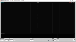
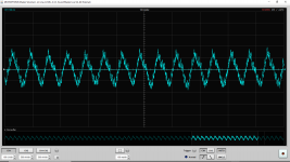
On a 5uV scale using a 60 dB LNA here is VCCA_R. First is locked to optical but idle and the second is with 1kHz full scale.
I would love to see such data posted from other approaches (such as op-amp buffer, specialized Ti or LT regulators, discrete regulators, discrete references, etc) to help inform my decisions on my modifications.
I would love to see such data posted from other approaches (such as op-amp buffer, specialized Ti or LT regulators, discrete regulators, discrete references, etc) to help inform my decisions on my modifications.
Attachments

Last edited:
We would all love to see that. Looking forward to your continuing contributions to the thread 🙂
One concern though, a lot of noise crud may be getting missed as a result of the rather limited bandwidth data acquisition sample rate.
One concern though, a lot of noise crud may be getting missed as a result of the rather limited bandwidth data acquisition sample rate.
Last edited:
So now the DVCC noise is not getting all over the board. The separate supply for DVCC is attached (power and ground) to the Tantalum DVCC bypass on the top of the board. The ferrite bead for DVCC is removed to detach it from the 3.3V power buss on the PCB.
here: DAC chip decoupling
and here:
ES9038Q2M Board
Yes, thank you. I will take some time to read and understand what JohnW posted. At the end of this journey I might still end up with dedicated regs and separate transformers and/or windings. (But first I will get close to exhausting the existing stock of discrete and transformers. Separate transformers is no problem as I have a fair graveyard from various obsolete or defunct equipment. However they are not "nice" transformer types.)
I have not played with the 1.2V core bypassing yet since I don't know what the internal LDO will tolerate without damage. (Or what will make it unstable.) What did you put on the 1.2V core LDO for bypassing? (DVDD?)
Can anyone make specific bypassing recommendations for the 1.2V core? I have not even probed that yet. For a variety of reasons I wonder what the ESD networks/tolerance are on the ES9038Q2M. In the middle of winter maybe a test point on the 1.2V core should be approached reluctantly.
Last edited:
In the link you provided are you intending to point towards JohnW's post or to the ones later on about the ceramic bypass capacitors very close to the pins (on the pins)?
I haven't found that separate transformer windings are needed for DAC chip non-AVCC pins. If opamp AVCC buffers run off +11v or whatever voltage the output stage opamps use, then I think they can be on same rail, depending. The reason I use separate winding for +-11v is so that I can use an upside down LT1083 for the -11v rail, and so that I can define the grounds for the two rails as getting tied together only at the dac board. Of course, when opamps share rails and grounds, then wires running to separate regulators will have some voltage drop due to each load current, which causes some power rail cross-talk that may not always be rejected enough by load device PSRR. However, if designing a 4-layer board with ground plane and internal fill areas for power rails, and also if regulators are located on the dac board, then the need for so many separate transformer windings becomes much less.
For prototyping or one-off designs where a custom board is not being designed and or regulators are not on the dac board, then the separate winding scheme is what I would prefer too.
For prototyping or one-off designs where a custom board is not being designed and or regulators are not on the dac board, then the separate winding scheme is what I would prefer too.
We would all love to see that. Looking forward to your continuing contributions to the thread 🙂
One concern though, a lot of noise crud may be getting missed as a result of the rather limited bandwidth data acquisition sample rate.
Yes. I am checking with the sound card and then occasionally with the 1Msps DAC/microcontroller scope. But that might be the limit for my equipment.
What did you bypass DVDD with on your board?
I suspect most of the noise comes from there based upon what I see on DVCC. I suspect that is coming "through" the internal 1.2V LDO from DVDD.
Bypass? Well, you could try the old .1uf X7R and a 10uf tantalum. There doesn't seem to be any reason to use fancy SMD film caps for digital rail bypass, and there are known reasons not to do it. Doesn't mean you can't try it to see what happens, but doubtful you will directly see signs of ringing with your present test gear.
Regarding maybe a more lossy ferrite bead in series with the DVCC load, you could try it and see. Even if it works, doesn't mean you shouldn't come back later and make sure its not having any small effect you don't like. Its just that the dac is still has enough bigger problems to mask some possibly much smaller things. Sometimes finding problems and making improvements tends to go in iterations.
Regarding maybe a more lossy ferrite bead in series with the DVCC load, you could try it and see. Even if it works, doesn't mean you shouldn't come back later and make sure its not having any small effect you don't like. Its just that the dac is still has enough bigger problems to mask some possibly much smaller things. Sometimes finding problems and making improvements tends to go in iterations.
Last edited:
I might try a little bit of careful experimenting with DVDD to see if anything changes with the noise that I am able to measure on DVCC and what gets over to the analog pins. I am reluctant to do much because I don't know that the internal LDO can tolerate. I don't know if I will achieve much in this case but dealing with noise at the source can help. Of course my main concern right now is very low frequency (85Hz) so I probably can't do anything about that.
I doubt the Tantalum caps on these boards have decent ESR. I do have some 1206 10uF and 47uF ceramic caps. I don't know if the internal LDO likes low ESR, however.
I wonder what ESS recommends on DVDD. Edit: CAP, 0603, CER, 1uF, 10%, 16V, X7R, TDK, C1608X7R1C105K080AC
Exactly the same for all five supply pins. Looks rather... ...uninspired. (Same thing on all pins, even with such huge differences in the types of pins and loads.) I guess it works, however.
Last edited:
I just started following this message board, so I apologize if this topic has been discussed before...
I am curious if anyone has tried measuring the noise spectrum of a constant DC output of one of these high-performance DACs? One can make a sound file of constant DC level and measure the noise spectrum of the output using a high-pass filter and a low-noise amplifier. This avoids dynamic range limitations and lets one measure the effect of noise of DAC voltage reference level. For example, comparing noise level at 0.01 V DAC voltage vs. 2 V would be interesting.
I am curious if anyone has tried measuring the noise spectrum of a constant DC output of one of these high-performance DACs? One can make a sound file of constant DC level and measure the noise spectrum of the output using a high-pass filter and a low-noise amplifier. This avoids dynamic range limitations and lets one measure the effect of noise of DAC voltage reference level. For example, comparing noise level at 0.01 V DAC voltage vs. 2 V would be interesting.
...
I wonder what ESS recommends on DVDD. Edit: CAP, 0603, CER, 1uF, 10%, 16V, X7R, TDK, C1608X7R1C105K080AC
well, the datasheet indicates:
"DVDD Supply
The ES9038Q2M is equipped with a regulated DVDD supply powered from DVCC. The internal DVDD regulator must be decoupled to DGND with a capacitor that maintains a minimum value of 1uF at 1.2V over the target operating temperature range. The recommended capacitor for decoupling DVDD is a 4.7uF ±20%, X5R 6.3V 0402."
JohnW has put 100uF there.
DVDD Experiments
Please note: These experiments are just for learning and gaining information.
It is not suggested that these are appropriate changes for others to make to their board.
DVDD is the output of an internal 1.2V LDO fed by the external 3.3V DVCC supply.
The purposes of the next experiments include trying to learn about:
Attached in order (without added 100uF Xicon):
Next post is with added 100uF Xicon.
Please note: These experiments are just for learning and gaining information.
It is not suggested that these are appropriate changes for others to make to their board.
DVDD is the output of an internal 1.2V LDO fed by the external 3.3V DVCC supply.
The purposes of the next experiments include trying to learn about:
1a. What sort of noise is on the DVDD?
1b. Is the largest noise component (the 85Hz seen on DVCC and VCCA) present on DVDD? Is that the source? Or is DVCC the source?
2. Does the observed DVDD noise signature appear on the other pins (DVCC, VCCA, AVCC)?
3. Does a DVDD bypass capacitor change noticeably change the noise seen on DVDD?
[Very little change is expected due to the low frequency of the 85Hz noise component and the low impedance.]
4. Does a DVDD bypass capacitor change noticeably change the noise seen on VCCA, AVCC?
[Very little change is expected due to the low frequency of the 85Hz noise component and the low impedance.]
Due to concerns that the internal LDO might become unstable and/or become damaged I did not use a low ESR or huge capacitor for the experiment. Instead a relatively high ESR capacitor was chosen. (Xicon 100uF 25V electrolytic.) That is already a pretty large capacitor to place here. But the idea is to modulate and measure to see what can be learnt from the perturbation.1b. Is the largest noise component (the 85Hz seen on DVCC and VCCA) present on DVDD? Is that the source? Or is DVCC the source?
2. Does the observed DVDD noise signature appear on the other pins (DVCC, VCCA, AVCC)?
3. Does a DVDD bypass capacitor change noticeably change the noise seen on DVDD?
[Very little change is expected due to the low frequency of the 85Hz noise component and the low impedance.]
4. Does a DVDD bypass capacitor change noticeably change the noise seen on VCCA, AVCC?
[Very little change is expected due to the low frequency of the 85Hz noise component and the low impedance.]
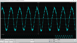
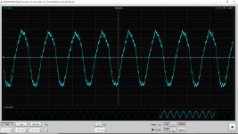
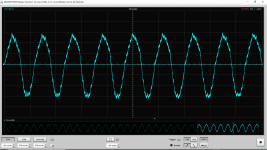
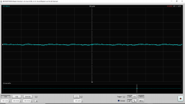
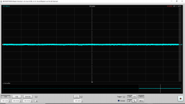
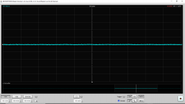
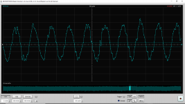
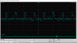
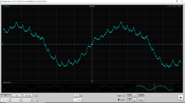
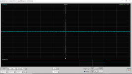
Attached in order (without added 100uF Xicon):
- DVDD
- DVDD (different timebase)
- DVCC
- VCCA
- AVCC_R (5uV scale)
Next post is with added 100uF Xicon.
Attachments
-
 DVDD All Battery Powered Optical Locked Time Base.png98.2 KB · Views: 250
 -
 DVDD All Battery Powered Optical Locked.png101.3 KB · Views: 243
 -
 DVCC All Battery Powered Optical Locked Time Base.png85.1 KB · Views: 254
 -
 VCCA All Battery Powered Optical Locked Time Base.png47.5 KB · Views: 251
 -
 AVCC_R 5uV All Battery Powered Optical Locked Time Base.png96 KB · Views: 255
Last edited:
Maxwell3,
Could be some discussion along similar lines to what you are interested in:
ESS Sabre Reference DAC (8-channel) ...Starting from post #2643 in that thread.
Could be some discussion along similar lines to what you are interested in:
ESS Sabre Reference DAC (8-channel) ...Starting from post #2643 in that thread.
- Home
- Source & Line
- Digital Line Level
- ES9038Q2M Board