kozard,
There are some old posts by JensH and maybe some other people:
https://www.diyaudio.com/forums/digital-line-level/314935-es9038q2m-board-6.html#post5296728
https://www.diyaudio.com/forums/digital-line-level/314935-es9038q2m-board-42.html#post5383506
IIRC, JenH said in a later post that the I/V outputs of his current mode output stage went into the analyzer in differential mode.
There are probably some other old measurements too. In the case of your measurements there may be various measurement setup issues to troubleshoot. Ground noise from USB or SPDIF, dac power supply noise, computer noise getting into sound card, etc. A number of potential pitfalls to rule out or else find and fix.
Thank you for the old measurements.
They don't look like my spectrum with the huge 200Hz & 15.6kHz spikes/spurs. No sign of that mess in your spectrum.
So I wonder if I have a defective board or ES9038Q2M chip?
it is not very clear for me what and how you are measuring. as well as how much EMI noise etc you pick up upon the measurement. there are enough good AN from Ti and others regarding basic setups for this.
you may check what is going on the board, if you have an oscilloscope and know how to use it.
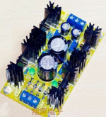
regarding those LDOs, most of them are very good and ecologically clean for consumer electronics. that is what they have been designed for.
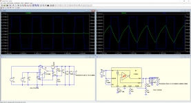
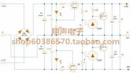
low noise is not the single most important parameter for PS. low enough and flat in audio range output impedance, and related load transient response matters very much here. this has been discussed, simulated and measured. here I attach a sim by Pavel Pogodin, posted on another forum for 50kHz/10mA load). I am not claiming that this is a final truth and now everyone should do like this, but practical results are clearly in favour of discrete regs for audio as well.
Attachments
Last edited:
Here are some more measurements after attempting to deal with supply noise at the noise sources.
Since there are ferrite beads all over the board I thought I would try to use them to an advantage and suppress noise from the sources getting to the sensitive clock and analog pins.
What I did was Noise Source > Low ESR OS-CON > Ferrite Bead > Power Buss > Ferrite Bead > Low ESR OS-CON > Analog Pins
Edit: To be more accurate (and considering the caps already on the power buss it is more like):
Noise Source > Low ESR OS-CON > Ferrite Bead > Power Buss & Existing Supply Capacitors > Ferrite Bead > Low ESR OS-CON > Analog Pins
So: Noise Sources > Shunt C > Series L > Shunt C > Series L > Shunt C > Sensitive Pins
Since the problem was not modulated I suspect the problem is not noise or supply related. If it was I would expect at least some response from the changes.
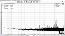
In the below measurements the Sine waves are at (in order): 1kHz, 2kHz, 4kHz, 6kHz and 8kHz.
1kHz, 2kHz, 4kHz are not too bad, especially consider we are at -9 dBFS (to avoid overloading my ADC).
But at 6kHz and 8kHz the results suddenly and greatly degrade.
Any ideas?
Since there are ferrite beads all over the board I thought I would try to use them to an advantage and suppress noise from the sources getting to the sensitive clock and analog pins.
What I did was Noise Source > Low ESR OS-CON > Ferrite Bead > Power Buss > Ferrite Bead > Low ESR OS-CON > Analog Pins
Edit: To be more accurate (and considering the caps already on the power buss it is more like):
Noise Source > Low ESR OS-CON > Ferrite Bead > Power Buss & Existing Supply Capacitors > Ferrite Bead > Low ESR OS-CON > Analog Pins
So: Noise Sources > Shunt C > Series L > Shunt C > Series L > Shunt C > Sensitive Pins
Since the problem was not modulated I suspect the problem is not noise or supply related. If it was I would expect at least some response from the changes.
In the below measurements the Sine waves are at (in order): 1kHz, 2kHz, 4kHz, 6kHz and 8kHz.
1kHz, 2kHz, 4kHz are not too bad, especially consider we are at -9 dBFS (to avoid overloading my ADC).
But at 6kHz and 8kHz the results suddenly and greatly degrade.
Any ideas?
Attachments
-
 OS CON on Clocks Digital Supplies 1kHz.png115.6 KB · Views: 283
 -
 OS CON on Clocks Digital Supplies 2kHz.png113.6 KB · Views: 273
 -
 OS CON on Clocks Digital Supplies 4kHz.png116.3 KB · Views: 265
 -
 OS CON on Clocks Digital Supplies 6kHz.png115.3 KB · Views: 265
 -
 OS CON on Clocks Digital Supplies 8kHz.png115.2 KB · Views: 120
Last edited:
There are probably some other old measurements too. In the case of your measurements there may be various measurement setup issues to troubleshoot. Ground noise from USB or SPDIF, dac power supply noise, computer noise getting into sound card, etc. A number of potential pitfalls to rule out or else find and fix.
The measurement setup does not show any similar problems with the LJM CS4398 or the AK4396:
Measurements of LJM CS4398 USB DAC With NJM4580D
Measurements of AK4396 DAC with REW
So I don't think it is a measurement issue.
The supply is presently a discrete current source & shunt regulator type (for +/- 15V) and a regulated 9.6V supply (from Digitech/Harman International for musical instrument signal processing equipment) for the on-board LM7805.
Attachments
Last edited:
Kozard,
I would suggest to connect the only ground to your measurement system near where you want to probe. Then first connect the probe to ground at that point and see if there is ground noise. You can also wiggle or move around the probe cable and see if that changes what you see. Another thing you might try is connecting the probe tip to its ground and wave the two in air right around the area you want to probe. Depending on the ground to tip short length and its loop area you can get some idea of how much radiated noise there is around there that might couple into your measurement.
I would also be very leery about using ferrite beads and some unstated value and type of oscon DC blocking cap. Better to put a good quality rolled film and foil film cap of sufficient uf inside a shielded box just before the sound care input. Keep the cap away from stray electromagnetic fields. To choose an appropriate cap you should figure out or look up the input impedance of the soundcard, or otherwise verify that the cap and probe system are working properly.
Ad hoc probe ideas that are not tested and verified before use are as likely to cause their own problems as they are to attenuate stuff you don't want to see. There is a forum member named Victor that can make you a fixed frequency ultra-low distortion analog oscillator board (-140dB HD, or maybe a little less). You just put it in a case and add a 1st stage voltage regulator for it. Then you have something you can use to test your soundcard, probe, etc.
EDIT: See that you posted using the same test setup with other dac boards. Still may be a good idea to do some checks in this case. This dac runs from a 100Mhz clock and just that may make some difference.
Last edited:
this has been discussed, simulated and measured. here I attach a sim by Pavel Pogodin, posted on another forum for 50kHz/10mA load). I am not claiming that this is a final truth and now everyone should do like this, but practical results are clearly in favour of discrete regs for audio as well.
The LT3042 is not in the best configuration, using a bypassed SET resistor only, as shown, but keep the PGFB disabled provides the best performance. Also, for an apple to apple simulation/measurement comparison, the LT3042 ILIM current limiting resistor should be set to zero (no current limiting). And the "discrete" schematic uses as a reference an ideal 2.5V voltage source (decoupling it is useless, BTW, it has a zero impedance at all frequencies anyway) which is, ahem, a rather gross approximation.
Last edited:
The OS-CON are not blocking caps. They are added to the board as 3.3V supply decoupling capacitors.
For example, the board has a ceramic cap to decouple the clock power supply pin (after a ferrite bead). I added the 560uF 6.3V Panasonic OS-CON (6SEPC560MW) across that existing 1206 ceramic decoupling capacitor.
In effect (on the 3.3V power distribution network on the board) I have created a series of CLC filters:
So: 3.3V Supply Noise Source > Shunt C OS-CON Decoupling Cap > Series L > Shunt C (Existing Stock Decoupling Caps) > Series L > Shunt C OS-CON Decoupling Cap > Sensitive 3.3V Pins
Last edited:
kozard,
Okay, understand.
I can tell you that ferrite beads are usually avoided in high end audio gear. I tried adding one to isolate clock noise on the clock power rail (for my AK4499 project), which was part of another set of experiments to help optimize power quality. I just did it, didn't tell anyone. Next time one of my audio designer friends came over to listen he got really excited in a not good way. He said, "What did you do?!" "All the depth is gone!" "If you loose that you will never get it back!" Fortunately, I keep track of every experimental change, so I can roll back things that don't work. Removing the ferrite bead fixed the problem. That said, I have used some ferrites to good effect in other cases, but have to make sure its helping rather than hurting. To avoid the risk of starting arguments all over again I will leave it at that.
Last edited:
I don't know the details of the example you cite. However if you add a ferrite bead it might be necessary to simultaneously add additional decoupling (might be substantial) otherwise you may have created a high impedance (at a certain range of frequencies) on a supply pin. (The opposite of what you want.) So perhaps such a change can not be made in isolation. In this case the ferrites are not added (are already exist on the stock board) and on each side there are now ceramic bypasses (stock), tantalum (stock) and now added Panasonic OS-CON.
So we are now much lower impedance across a broader frequency range than stock.
If the board was stock without ferrite beads then just adding them alone would have resulted in high impedance across a broad range of frequencies that depend on the impedance characteristics of the bead used. (And assuming small and low cost stock bypasses. I have not removed the stock tantalum caps to measure but I doubt they are low ESR/higher cost versions.)
Now it would be better to have individual low noise regulators and proper bypassing at each sensitive pin. However I am debugging a gross problem in an attempt to reach a reasonable starting point before major surgery.
Last edited:
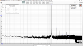
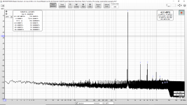
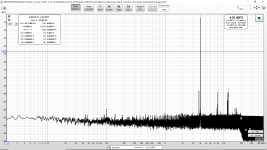
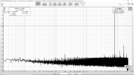
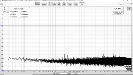
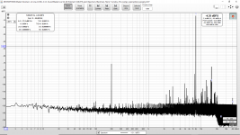
Take a look at these measurements (all 8kHz sine being generated by the ES9038Q2M & REW software) using the coaxial input. I think we have found the first major/gross problem.
The first is a sample rate of 44.1kHz from the computer/SB0490.
The second is a sample rate of 48kHz from the computer/SB0490.
The third is a sample rate of 88.2kHz from the computer/SB0490.
The fourth is a sample rate of 96kHz from the computer/SB0490.
So the first/most major problem seems to have nothing to do with the analog side/supplies/output section. Instead it appears to be on the digital side related to sample rate. We can turn it on and off by picking the sample rate.
Any suggestions/ideas? I have not seen this before. Has anyone else seen something like this with the coax input?
Attachments
-
 OS CON on Clocks Digital Supplies 8kHz 44p1kHz Rate.png115.7 KB · Views: 128
 -
 OS CON on Clocks Digital Supplies 8kHz 48kHz Rate.png125.8 KB · Views: 122
 -
 OS CON on Clocks Digital Supplies 8kHz 88p2kHz Rate.png149 KB · Views: 120
 -
 OS CON on Clocks Digital Supplies 8kHz 96kHz Rate.png115.2 KB · Views: 113
Last edited:
practical results are clearly in favour of discrete regs for audio as well.
Do you have any concrete evidence (e.g. measurements) for this sweeping statement or is this just something you read from some forum?
Last edited by a moderator:
When it comes to ferrites, I would question whether generated hysteresis distortion of the power line voltage could be an issue. Bruno Putzeys on hysteresis distortion: This Thing We Have About Hysteresis Distortion - PURIFI
EDIT: Another factor that can be a problem in very sensitive circuits is piezoelectric effect in ceramic capacitors. Hi-Z ceramics tend to be the worst in that respect, even X7R has enough to sometimes be a problem. https://product.tdk.com/en/contact/faq/31_singing_capacitors_piezoelectric_effect.pdf
And: https://sh.kemet.com/Lists/TechnicalArticles/Attachments/88/2006 07 ArrowAsiaTimes - MLC Noise.pdf
It can also work the other way around, physical flexing of a ceramic cap can generate a voltage. When such caps are SMD mounted on thin PCBs, flexing of the board due to mechanical vibration can produce measurable noise generation from the caps. Of course, many applications are insensitive to such small non-idealities. Some audio circuits may or may not be sensitive. Sometimes experiments and or tests may be used to find out if there is any issue.
Last edited:
Quote:
Originally Posted by kozard
...deleted... ...it was not posted by kozard
Do you have any concrete evidence (e.g. measurements) for this sweeping statement or is this just something you read from some forum?
Pardon me but you quoted "eziitis" from post #6622 but you edited the quote tag to make it look like you were quoting me.
Pardon me but I did not post any such thing.
The LT3042 is not in the best configuration, using a bypassed SET resistor only, as shown, but keep the PGFB disabled provides the best performance. Also, for an apple to apple simulation/measurement comparison, the LT3042 ILIM current limiting resistor should be set to zero (no current limiting). And the "discrete" schematic uses as a reference an ideal 2.5V voltage source (decoupling it is useless, BTW, it has a zero impedance at all frequencies anyway) which is, ahem, a rather gross approximation.
Right, LT3042 is a very good reg, and no doubts the discussed board would benefit from it at some extent. But that is not the point. Virtually all commercial DACs are designed departing from “indispensable and sufficient “ to have a market share and make a profit. In contrast here in DIY world we can afford go beyond this and construct the things that not qualify above but please us. And share views and feelings. Of course some common sense should be still with us 😀
Sorry, multi-quote typo.Pardon me but you quoted "eziitis" from post #6622 but you edited the quote tag to make it look like you were quoting me.
Pardon me but I did not post any such thing.
practical results are clearly in favour of discrete regs for audio as well.
Do you have any concrete evidence (e.g. measurements) for this sweeping statement or is this just something you read from some forum?
Take a look at these measurements (all 8kHz sine being generated by the ES9038Q2M & REW software) using the coaxial input. I think we have found the first major/gross problem.
The first is a sample rate of 44.1kHz from the computer/SB0490.
The second is a sample rate of 48kHz from the computer/SB0490.
The third is a sample rate of 88.2kHz from the computer/SB0490.
The fourth is a sample rate of 96kHz from the computer/SB0490.
So the first/most major problem seems to have nothing to do with the analog side/supplies/output section. Instead it appears to be on the digital side related to sample rate. We can turn it on and off by picking the sample rate.
Any suggestions/ideas? I have not seen this before. Has anyone else seen something like this with the coax input?
Have you tried running loopback on your soundcard at that frequency and sample rates?
Do you have any concrete evidence (e.g. measurements) for this sweeping statement or is this just something you read from some forum?
Why assume those are the only two possibilities?
Do you have any concrete evidence (e.g. measurements) for this sweeping statement or is this just something you read from some forum?
Yes, I have compared and measured impact of some monolithic regs and some discrete ones in several PS setups for ESS DACs. Particularly for AVCC and I/V-LPF supplies. Do I owe you any report on my research?
Are you implying that discrete regulators are better based on what you hear? If it is based on purely subjective opinions then no sweeping statements should be made. You should at least add something like "in my experience" to your statement.
Yes, I have compared and measured impact of some monolithic regs and some discrete ones in several PS setups for ESS DACs. Particularly for AVCC and I/V-LPF supplies. Do I owe you any report on my research?
If you have real measurements to back your statements why do you post irrelevant simulations as in post #6622?
- Home
- Source & Line
- Digital Line Level
- ES9038Q2M Board