So it's on AES site for which i have to pay money to see anything there and not here...Well...in my experience the best things come for free!
Clearly you are not good at reading
CHANNEL D - Download it's there for free.
Of course. It's been posted on here enough times anyway.
Ok then...Is it posted here or on ChannelD site? Before asking me for any proof let me see yours!Personally i don't give a damn on anything you say on audio or anything related...Are you ok with that?If so, please ignore anything i say!No I don't. Stop playing the textbook internet troll when asked a question.
Or just go to ChannelD website, read their AES paper and come back with a critique why they are wrong.
Last edited:
Bravo, in almost all threads where I came across your postings, you managed to insult people with your attitude, even the most polite and well mannered ones.
Hans
Hans
Not yet, probably worth trying.
BTW, I still love the OPA627 and I would like to mention that sometimes the real-life circuit results are not so straightforward as expected.
I think I'm dozens of posts behind with this one, but, yes we still hear a lot about OPA627! Low frequency noise along with low input bias current make for a very popular amplifier. Similar technology (with JFET input) is OPA1642 or OPA828, low frequency (LF) noise is very good on those devices as well. Since the gain is higher at LF on the RIAA circuit, LF noise is of course very important.
Thank you for making me aware of the OPA828, positioned as the successor of the OPA627, being one of my favourites.
It’s amost dazzling how many competing opamps are brought to the market and hard to see what the differences and the benefits are supposed to be, because they are all so alike.
Hans
It’s amost dazzling how many competing opamps are brought to the market and hard to see what the differences and the benefits are supposed to be, because they are all so alike.
Hans
Without Cart in posting #69
And with the Cart connected
Hans
When it says "input shorted", you know it's nonsense.
And with the Cart connected
😀😀😀You ignore the mechanical transfer of the cart, so what you simulate is nonsense anyway
Hans
I think I'm dozens of posts behind with this one, but, yes we still hear a lot about OPA627! Low frequency noise along with low input bias current make for a very popular amplifier. Similar technology (with JFET input) is OPA1642 or OPA828, low frequency (LF) noise is very good on those devices as well. Since the gain is higher at LF on the RIAA circuit, LF noise is of course very important.
Looking at the noise specs, those op-amps are both very suitable for moving magnet amplifiers, but what you wrote about LF noise is only correct when you are interested in the unweighted noise at the RIAA amplifier output.
When you take into account RIAA and A-weighting or RIAA and ITU-R 468 weighting and assume that the voltage noise is partly white and partly 1/f, what matters most is the noise density at 1162 Hz and 2897 Hz, respectively. For a given noise density at 1162 Hz or 2897 Hz (or 1169 Hz for A-weighting and IEC-modified RIAA), you always get the same total output noise no matter what part of the noise is white and what part 1/f.
I know JFET noise can have more exotic frequency dependencies than just white or just 1/f, I never tried to find a break-even frequency for those. Still, the fact remains that the bass boost of the RIAA correction is slower than the low-frequency roll-off of A- or ITU-R 468-weighting filters.
Attachments

Last edited:
Did you take the usual precautions: long enough settling time, switched off waveform compression, tight accuracy settings and so on?
By the way, I don't think this will help you with your distortion issue, but an acquaintance of mine once measured the impedance of a Shure V15-III and much later, I made a LTSpice model for it. It includes iron losses and parasitic capacitance, but no mechanical transfer. See the attachment. C10 and R5 are the load, so they are no part of the cartridge.
Marcel, thank you very much.
Can you please specify which units those are: ohms, mH, nF or pF, etc.? You only mention those on the right, which are obviously the cartridge load.
Bill started his attacks long ago in every topic of mine regarding phono circuits.If i disregard somebody's opinions i simply do it based on my own opinions.If I tell that publicly i usually give an argument.Bill never gave any solid argument for his views.Should i Read Channel D publications in search of that AES paper that might prove me wrong? I won't do it. My time on Earth is limited.Bravo, in almost all threads where I came across your postings, you managed to insult people with your attitude, even the most polite and well mannered ones.
Hans
.If you have "proof" for me being insulting in almost every thread you're free to say anything on that.I might have been insulting to Bill's attitude.That i can't deny.I already said i don't give a damn on his opinions as he never back up his own opinions so i'm not obliged to do it either.
Every time you got in my topics you talked about theoretical things i don't quite get so i never replied to your posts as i can only listen to you. This time might be the only time answering you as this is the only thread written by you that i can understand.
Last edited:
I post a link to the website and you just snark back. You really need to calm down, esp following your hissy fit in 'forum problems' recently. Your comment on dirty records still stands as something you have pulled out of nowhere and are not even willing to try and defend. We are hear to have a debate on things not accept folklore. So if you say something you should be prepared to back it up.
i don't see any link here:
https://www.diyaudio.com/forums/ana...vs-bjt-input-phono-preamp-24.html#post6364196
https://www.diyaudio.com/forums/ana...vs-bjt-input-phono-preamp-24.html#post6364196
The link was above.
Without Cart in posting #69
And with the Cart connected
😀😀😀
Hans
Yes, you sometimes need different simulation testbenches or different measurement set-ups for different parameters. At work I often use dozens of simulation testbenches for the same circuit. That's one of the reasons why simulators support hierarchies: you can use different top levels for the simulation testbenches and put the circuit under test in a subcircuit that is instantiated in all of them.
If you are prepared to restrict yourself to one and only one type of cartridge and manage to get accurate data on its mechanical response and its impedance magnitude and phase, then you can make a cartridge model that includes the mechanical transfer and that accurately models the impedance, and just simulate the response from stylus velocity to amplifier output voltage. You can then try to optimize the response of the cartridge plus amplifier combination and use the same set-up for the frequency response and the noise.
I saw it now...The pdf documents are very clear on the possibility to saturate the adc input while the full document put an emphasis on DIGITAL reconstruction filter and digital removal of clicks and pops...Besides i can't see the schematic of that preamp so i have no idea what the preamp itself does to the sound either...Even so, there's a very clear indication of digital processing of the recorded signal for pop-clicks removal with Pure Vinyl whatever that might be...
Last edited:
Marcel, thank you very much.
Can you please specify which units those are: ohms, mH, nF or pF, etc.? You only mention those on the right, which are obviously the cartridge load.
The values on this schematic https://www.diyaudio.com/forums/att...277-fet-vs-bjt-input-phono-preamp-figure4-png are almost all in scientific notation and they are all in ohm, henry and farad. So 28.75E3 for R2 means 28750 ohm or 28.75 kohm.
Would I be abusing your courtesy if I asked you to put all the values in non-scientific notation?
If you are prepared to restrict yourself to one and only one type of cartridge and manage to get accurate data on its mechanical response and its impedance magnitude and phase, then you can make a cartridge model that includes the mechanical transfer and that accurately models the impedance, and just simulate the response from stylus velocity to amplifier output voltage. You can then try to optimize the response of the cartridge plus amplifier combination and use the same set-up for the frequency response and the noise.
Why restrict? I have miniDSP as a preamp, this allows me to optimise for each cartridge. I'm not the sort to change cartridges every week so the setup time is not an issue for me.
Of course it may be that there is no audio band mechanical issues that need correction on the average cartridge. I would be happy if that turned out to be the case.
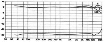
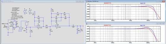
Using Marcel's replacement circuit for the V15III in Carlmart's circuit, I tried to add the mechanical resonance, thereby looking at Stereophile's recorded FR for both 170pF and 500pF, assuming a cable capacity of 100pF to be added.
Result is below in both images, showing the FR before (red) and after the resonance filter behind the output (Blue).
It's clear that the real thing is even more complex because of secondary resonances in the cantilever, but as a first approximation it comes quite close to the recorded FR.
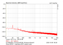
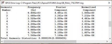
When offering a 8500Hz signal producing 280mV rms at the output, distortion is below ppm level as shown below.
Hans
Result is below in both images, showing the FR before (red) and after the resonance filter behind the output (Blue).
It's clear that the real thing is even more complex because of secondary resonances in the cantilever, but as a first approximation it comes quite close to the recorded FR.
When offering a 8500Hz signal producing 280mV rms at the output, distortion is below ppm level as shown below.
Hans
Attachments
Last edited:
- Status
- Not open for further replies.
- Home
- Source & Line
- Analogue Source
- FET vs BJT input phono preamp