if used with +-15v supply there's nothing you can hear better with any op-amp on the market than what you can get with OPA2228P.This is a very good op-amp.
Noise-wise the OPA2228 is a good choice for moving magnet: slightly better noise specs than an NE5534A
and realistic measuring conditions for the noise current, unlike some Linear Technology parts.
So which do you say that 750 ohm should be then?
That 750 ohm is fine, but a ten times larger value would also be fine.
OK, so why there is the elevated unexpected noise with the AD797? Because of the HF oscillations, that cannot be disclosed by audio band measurements.
O.K. it's true that oscillations will fold back into the noise spectrum when sampling with a much lower frequency, thereby seemingly elevating the noise.
But did you try anything to stop these oscillations like inserting a resistor into the supply lines or connecting the decoupling caps to each other instead of also connecting them to gnd ?
I have never seen oscillations with the AD797 in different designs, but I have always used 2.2R resistors in the power lines plus 10nF//22uF as close as possible.
Hans
P.S. I have a 100MHz digital scope
Last edited:
That 750 ohm is fine, but a ten times larger value would also be fine.
OK, I have been playing with different values for the 750 ohms resistor.
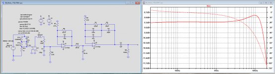
No one seems to have commented anything on that experiment I did, replacing Borbely discrete stages with LT1792s. So I wonder if this is I'm trying is something valid, something realistic, that the results the simulation shows mean there's an actual improvement or is just a theoretical game, to call it somehow.
What I did was play with that resistor only, and when I get to 2K18 the FR curve gets flatter than with 750, at least on the hump on the right, which is present in all simulations with the Shure V15 load. If I increase the resistor value further the FR curve starts to get weird.
What I would like to know is if such results are meaningful, have any significance. I'm pretty sure this experiment has been carried out by many people, perhaps Borbely himself.
In the end all these things have any meaning if they improve anything on the audio quality.
Attachments
Do you keep the time constant R10 C1 constant, that is, change C1 inversely proportionally to R10?
You mean that if I increase R10, then to decrease C1 in the same proportion, right?
But I was looking at flattening the response curve. I guess that is not allowed then.
But I was looking at flattening the response curve. I guess that is not allowed then.
Ah, I didn't understand that. If you want to flatten the response by tweaking time constants, I think it is better to do that in real life using a test record, assuming those are accurate enough - I haven't a clue if they are, but Bill probably knows. The problem with using the simulation for flattening the response is that there are two things missing from the simulation model: the mechanical transfer of the stylus-cantilever-magnet and the iron losses of the inductor. Both have an impact on the response.
Without test record or information about the mechanical transfer and iron losses, the best you can do is assume that the cartridge designer has done his/her/its job properly and that you overall get a fairly flat response from stylus velocity to output voltage when the cartridge is working with its recommended load. That is, just short out L1 and R4 when you look at the frequency response, and put them back in when simulating noise.
Without test record or information about the mechanical transfer and iron losses, the best you can do is assume that the cartridge designer has done his/her/its job properly and that you overall get a fairly flat response from stylus velocity to output voltage when the cartridge is working with its recommended load. That is, just short out L1 and R4 when you look at the frequency response, and put them back in when simulating noise.
Another thing I can do is to leave things as the original designer designed, like EB.
My main question had been if, considering the limitations simulations seem to have, like the models, if equalizing things as EB did on his discrete preamp is really feasible or not quite so.
Can you comment on that? Or it's a question of assembling and see what it turns out?
My main question had been if, considering the limitations simulations seem to have, like the models, if equalizing things as EB did on his discrete preamp is really feasible or not quite so.
Can you comment on that? Or it's a question of assembling and see what it turns out?
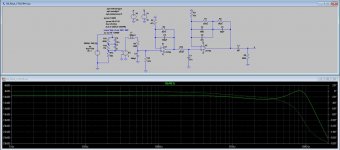
O.k. here it is, see the image below.No one seems to have commented anything on that experiment
First of all I have replaced your anti riaa network with a more accurate one.
Second, I have replaced the rather huge cap at the input to 150pF.
And since the passive network should have a RC time of 75usec, I changed your C1 into 34n4.
The FR response as a result of that is shown in the image and is caused by the Cart.
It is possible to make this flatter by letting the 75usec pole be taken over by a much lower input resistance as the 47K you are using, with two disadvantages
1) every Cart will need a different termination resistance and
2) you will loose some S/N, but this amp produces so very little noise that it will not be a point to worry about,
I have also taken the opportunity to change the LT1792 for an OPA1656 and a-weighted the output noise, but the difference in noise production was only marginally in favour of the OPA1656.
Hans
Attachments
Another thing I can do is to leave things as the original designer designed, like EB.
My main question had been if, considering the limitations simulations seem to have, like the models, if equalizing things as EB did on his discrete preamp is really feasible or not quite so.
Can you comment on that? Or it's a question of assembling and see what it turns out?
As long as Erno Borbely didn't use tricks like tweaking the RIAA circuit values to compensate for finite loop gain, his topology and component values should also work for an op-amp implementation. I would also expect the simulations of the transfer to be quite reliable as long as you don't include the cartridge (for the reasons explained in post #267).
Any way to add that mechanical transfer to the variables?
It's essentially a second-order low-pass, but the trick is to get the parameters right. Bill (billshurv) probably knows more about it, as he likes to experiment with non-standard termination impedances and equalization.
Marcel, thank you for your friendly words.
To calculate the S/N with the cart connected it is not al all nonsense but in fact very accurate, but you know all that, don't you.
Hans
To calculate the S/N with the cart connected it is not al all nonsense but in fact very accurate, but you know all that, don't you.
Hans
Apologies for the blunt one-liner, but I already wrote the same more politely three posts higher.
I think you either need separate simulation schematics for noise and for RIAA conformity, or need to divide out the transfer from cartridge model EMF to amplifier input terminal voltage when you look at the RIAA conformity, or need to use a parameterized resistor to short out the cartridge impedance for the RIAA conformity simulations (something like Rshort = 0.01 during RIAA conformity simulations, 1E9 when simulating noise) .
I think you either need separate simulation schematics for noise and for RIAA conformity, or need to divide out the transfer from cartridge model EMF to amplifier input terminal voltage when you look at the RIAA conformity, or need to use a parameterized resistor to short out the cartridge impedance for the RIAA conformity simulations (something like Rshort = 0.01 during RIAA conformity simulations, 1E9 when simulating noise) .
Last edited:
Any way to add that mechanical transfer to the variables?
What you need is the real life measured FR.
Weaponed with that information, you can make changes to the termination.
But since the Cart in combination with the termination capacitance is a second order LC system, you will become almost independent of the capacitance value with a much lower termination.
There is nothing you can do to influence the mechanical properties.
But in general the manufacturer has include the mechanical resonance in the FR and has made the Cart to work optimally with 47K and 150pF.
Hans
It's essentially a second-order low-pass, but the trick is to get the parameters right. Bill (billshurv) probably knows more about it, as he likes to experiment with non-standard termination impedances and equalization.
I would like to.... Tantilising close, but work and kids are getting in the way. I'm litterally 1 cable and a circuit check away now from trying to tease out the mechanical response from the electrical.
Shure recommends 450 pF for the V15-III, but on Stereophile's plots, it looks flatter with a smaller capacitance:
Shure V15-III phono cartridge | Stereophile.com
Unfortunately the recommended load capacitance is different for each cartridge model, and you have to subtract the cable capacitance to find the right termination capacitance.
Shure V15-III phono cartridge | Stereophile.com
Unfortunately the recommended load capacitance is different for each cartridge model, and you have to subtract the cable capacitance to find the right termination capacitance.
Well, sorry to say but now I definitely know something is not right in that cartridge we are using on the simulation.
For the first time I loaded it on the simulation I had for the discrete Luxman 5C50, which is the best RIAA preamp I have ever heard, always using a Shure V15III.
The FR seems to look "fine" not much different from the others I saw using the cart model load.
But what I got when looked at the THD, with the same 300mV input and 8400Hz was very poor. And this had been a preamp that had had brilliant, superb results in the reviews from the time it was released.
So I'd say something is not right in this load.
So, Marcel, what should we do to get to more reliable results, something we might look at and be more sure it means something when the preamp is used?
It seems to be a matter filled with interrogation marks, and very few answers.
Am I exaggerating?
Did you take the usual precautions: long enough settling time, switched off waveform compression, tight accuracy settings and so on?
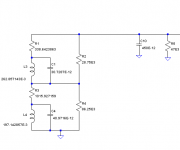
By the way, I don't think this will help you with your distortion issue, but an acquaintance of mine once measured the impedance of a Shure V15-III and much later, I made a LTSpice model for it. It includes iron losses and parasitic capacitance, but no mechanical transfer. See the attachment. C10 and R5 are the load, so they are no part of the cartridge.
By the way, I don't think this will help you with your distortion issue, but an acquaintance of mine once measured the impedance of a Shure V15-III and much later, I made a LTSpice model for it. It includes iron losses and parasitic capacitance, but no mechanical transfer. See the attachment. C10 and R5 are the load, so they are no part of the cartridge.
Attachments
- Status
- Not open for further replies.
- Home
- Source & Line
- Analogue Source
- FET vs BJT input phono preamp