So it's on AES site for which i have to pay money to see anything there and not here...Well...in my experience the best things come for free!
Are all these preamps also meant for both mc/mm.Attached is the first stage and passive Low Pass of a two stage RIAA amp published by Erno Borbely. In the article he makes a comment that he has been able to reduce the value of the series resistor in the LP filter (R36) to 750 ohm for noise reasons. The JC published RIAA uses 1600 ohm, the Emerald 2K26 ohm and the Rotel is all the way up at 75K. Without having done the calculations, I suspect that the high impedances in the Rotel LP passive networks warrants the use of JFFET amp also in the second stage. The Emeralds value of 2K26 seem be good in the sense that most op-amps can drive this load and the filter network would pose a low source impedance for the second stage.
If not, you have your answer.
A mm produces roughly 10 times as much output, so said resistor may produce 10 times as much noise in the same 40dB setting , or be 75k.
With 30dB gain it should the be 7k5 and when using it in the 20dB position 750R.
So it all depends on the gain that will be needed.
Hans
Hans,
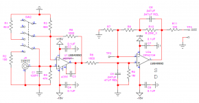
I will have to give that one a think. They all allow the same generic topology as indicated below with selectable gain for stage one and fixed gain for stage-2. The high frequency cut is by means of a passive filter between the two amps and the low frequency boost by active filtering in the last stage.
Had gain setting been in stage-2 I would have no issues following the argument. I may be overlooking something, but as as it stands I would have thought that the input amplifier (stage-1) determines the S/N and normalizes output level. Stage-2 noise would "only" need to have fixed gain and noise below the noise floor set by stage-1. Hence, I would assume the impedances of the passive filter between amplification stages to be of importance for the choice for stage-2 where high impedance networks may limit choice to low current noise devices (The Rotel comes with NE5534 with published upgrades suggesting to replace these with AD744)
The NAD and Borbely being the most advanced designs with discrete amplification in the first stage. Like the Borbely design, the NAD feature multiple gain setting where the other have two (mm/mc). The NAD has selectable current for the input LTP depending on MM/MC.
Attachments
Marcel, I know that you have done a lot of work on analysing noise in RIAA stages. I would appreciate if you could expand a bit on this topic. Specifically; how will the impedances of the passive network influence noise generated by the second stage?
Attached is the first stage and passive Low Pass of a two stage RIAA amp published by Erno Borbely. In the article he makes a comment that he has been able to reduce the value of the series resistor in the LP filter (R36) to 750 ohm for noise reasons. The JC published RIAA uses 1600 ohm, the Emerald 2K26 ohm and the Rotel is all the way up at 75K. Without having done the calculations, I suspect that the high impedances in the Rotel LP passive networks warrants the use of JFFET amp also in the second stage. The Emeralds value of 2K26 seem be good in the sense that most op-amps can drive this load and the filter network would pose a low source impedance for the second stage.
As the first stage in the Borbely design has a flat voltage gain over the audio band and R36 is in series with the first stage output, you can calculate the noise of R36 back to the input by dividing it by the first stage's voltage gain. So in the 20 dB mode, that's one tenth of the noise voltage of R36. That's equivalent to the noise produced by a resistor of one hundredth part of R36 straight at the input, as there is a square root in Vn = sqrt(4 k T R B). Hence, 750 ohm is equivalent to 7.5 ohm at the input in the 20 dB mode and 0.075 ohm in the 40 dB mode.
The second amplifier stage is driven from an RC network and the transfer from the input of the whole amplifier to the input of the second stage has a roll-off above 2122 Hz, so the second stage's voltage noise transferred back to the input rolls up from 2122 Hz onward. The second stage's noise current can be transformed to a current source across the first stage's output that doesn't do anything and one in parallel with R36, which can then be transferred to the input of the complete amplifier by multiplying with R36 and dividing by the first stage gain.
All in all, finding the exact optimum combination of voltage and current noise for the second stage gets complicated, but you can say straight away that when R36 is sized to have a negligible noise contribution, the impact of the noise current of the second stage will be at least equally negligible when it has a spectral density <= sqrt(4 k T/R36). That's about 4.65 pA/sqrt(Hz) for R36 = 750 ohm and 0.465 pA/sqrt(Hz) when R36 = 75 kohm.
Thanks, that makes sense.
I assume that the "exact optimum" you refer to is related to frequencies and IEC weighting.
Since the second stage will be doing bass boost, would you say that the nose current values for 100Hz is the most relevant to use for the second stage or would you use the 1kHz spec?
Lars
I assume that the "exact optimum" you refer to is related to frequencies and IEC weighting.
Since the second stage will be doing bass boost, would you say that the nose current values for 100Hz is the most relevant to use for the second stage or would you use the 1kHz spec?
Lars
There is no frequency dependence in the transformation of the second stage input noise current to the equivalent input noise voltage of the whole amplifier (just multiply with R36 and divide by the voltage gain of the first stage), so the relative importance of 1/f noise and white noise in the second stage input noise current is the same as for the voltage noise at the input of the whole amplifier. I once derived that when you read off the voltage noise at 1169 Hz, it makes no difference for the total RIAA- and A-weighted noise what part is white and what part is 1/f noise.
The Borbely amp has an input noise of ca. 1.2 nV/rtHz.
In the 40dB setting R36 can be seen as a 7.5R at the input.
7.5R produces 0.35nV/rtHz, thereby increasing the noise of this first stage by 0.36dB.
A 1500R resistor for R36 will increase the noise by 0.7dB
So it’s a matter how of far to the limit you want to go and the relevance should be seen in combination with the Cart being used, its output voltage etc.
With all the info at hand you will be able to calculate a S/N with the Cart connected and see what effect R36 will have.
Hans
All,
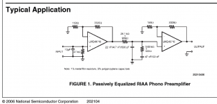
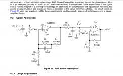
Marketing/systems guy from TI here - I didn't read through all of the threads here, but have you tried OPA1656? Exceptionally low noise for a FET input device. I put a RIAA circuit in the data sheet, see page 19.
Not yet, probably worth trying.
BTW, I still love the OPA627 and I would like to mention that sometimes the real-life circuit results are not so straightforward as expected. As an example, my OPENAMP open project phono preamp. It has a thread here
OPENAMP1 - MM phono preamp open project
and can be found at my web as well
Preamplifier for MM cartridge
where one can find complete schematics and BOM
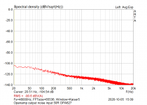
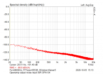
Best results were obtained with OPA627 at the position of the 1st opamp. Attached are measurements of the output noise RMS voltage and noise spectral density for OPA627, OPA134 and AD797, with input shorted with 50 ohm resistor (please note these are measurements and not the simulations). Measurements with cartridges were made in the past.
Attachments

Reading the Muffsy page it seems that he simulated using the LT1792/LT1037, but recommends using OPA2134/LM4562. In other words his PCB seem to be for dual op-amps and hence not very suited for "singles".
Yes, he did that, even if in my simulations I used the other opamps. Also replaced the LT1037 for another LT1792. Now I'm trying to use the OPA1652, which might be dual more affordable option to the 1792, which is not that cheap either.
My first choice would be the RJM Emerald. Single channel boards with two single op-amps per board. Active shunt regulation of the PSU. Available as a kit or as PCB-only.
RJM Audio - The Emerald Phono Stage
RJM Audio Emerald Phono Stage Help Desk
Now that seems to be an very good choice option! Using the original passive parts values (no MC option), but with the LT1792, I got the best results of all preamps.
As I also happen to have both OP27 and OP37 models for LTSpice, I also tried them, and the THD specs are even better.
FR curve has been flatter than all others. IMHO they are using a too low value output cap. Something like 4.7uF film cap would make it rule flat on the low bass. Maybe Emerald did it on purpose to control rumble or low frequencies.
BTW: I'm using a 300mV input now, and simulating for 8.4KHz, as Dreamth suggested. I remember there's a way to make LTSpice to simulate for several values at the same time, which might be interesting for different frequencies.
If I build this version, I could try and plug both chips and listen to the results, and compare them with the LT1792, which I still would have to buy.
I tried the OP37 on the second stage only, as it needs a minimum of x5 gain to keep stability.
My only question on the Emerald design is why they decided to use the first stage as a buffer, with no gain, and use a x348 gain in the second stage. Can someone explain that to me?
The arguments I've seen for this topology make make me lean towards this type splitt-Eq also. Borbely is not the only one to advocate this split passive LP active Bass boost.
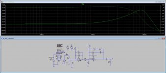
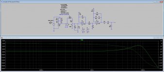
OK, now things started to be more interesting. I'm not sure is possible what I did, but I tried to repeat what Borbely had done on his discrete FET preamps, using the same resistor and capacitor values he used. And it seemed to work! At least on the simulation. Using the LT1792.
The THD is the lowest I got till now on any of the preamps. But that would have to be rechecked for 300mV input and 8.4KHz.
But it's lower than the Emerald, to start with.
The EB version FR curve is not as flat as the Emerald though.
The op-amp based design posted by J.Curl in a thread here on diyaudio, the Rotel Rq-970bx, the NAD S100 discussed previously in this thread and the above mentioned Emerald are other examples.
Which JC design is that? Available where?
I should try that Rotel and the NAB too and see what I get.
The asc files are those you can see THD.
Attachments
Not yet, probably worth trying.
BTW, I still love the OPA627 and I would like to mention that sometimes the real-life circuit results are not so straightforward as expected. As an example, my OPENAMP open project phono preamp. It has a thread here
OPENAMP1 - MM phono preamp open project
and can be found at my web as well
Preamplifier for MM cartridge
where one can find complete schematics and BOM
Best results were obtained with OPA627 at the position of the 1st opamp. Attached are measurements of the output noise RMS voltage and noise spectral density for OPA627, OPA134 and AD797, with input shorted with 50 ohm resistor (please note these are measurements and not the simulations). Measurements with cartridges were made in the past.
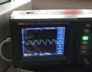
OK, so why there is the elevated unexpected noise with the AD797? Because of the HF oscillations, that cannot be disclosed by audio band measurements.
Attachments
if used with +-15v supply there's nothing you can hear better with any op-amp on the market than what you can get with OPA2228P.This is a very good op-amp.I have about 8 pcs and used some with tape heads preamps...really, really good.I think i'm gonna try the lme49710 passive network phono with opa2228.I have lme49710 as well, but opa2228P has 4 times lower noise.You have also the LM833 phono .
Attachments
Marcel, you are right, I obviously had some Borbely Corona short circuit.
With 40dB gain to produce 1/100 of the resistor noise at the output, you need a resistor that is 1/10,000 of that value at the input.
No math needed to prove that at all.
That makes the 750R output resistor rather ridiculously low.
In the 40dB position, to go as low as 75mR for an 1.2nV/rtHz MC input is not at all bringing any additional benefit and in the 20dB position 7.5R for an MM input with the same 1.2 nV/rtHz neither, but it doesn't hurt.
Hans
OK, so why there is the elevated unexpected noise with the AD797? Because of the HF oscillations, that cannot be disclosed by audio band measurements.
Can find the schematics for that MM preamp.
Marcel, you are right, I obviously had some Borbely Corona short circuit.
With 40dB gain to produce 1/100 of the resistor noise at the output, you need a resistor that is 1/10,000 of that value at the input.
No math needed to prove that at all.
That makes the 750R output resistor rather ridiculously low.
In the 40dB position, to go as low as 75mR for an 1.2nV/rtHz MC input is not at all bringing any additional benefit and in the 20dB position 7.5R for an MM input with the same 1.2 nV/rtHz neither, but it doesn't hurt.
Hans
So which do you say that 750 ohm should be then?
- Status
- Not open for further replies.
- Home
- Source & Line
- Analogue Source
- FET vs BJT input phono preamp