If the display and the buttons work, the processor is working. If the processor is working, it's putting out the PWM square waves, so the only thing else that could be wrong is the low pass filters. Check for bad solder joints and correct components. When in standby, the PWM outputs are at 50% so the DC output after the LPFs should be 2.5VDC.
Well I tried...built a new network and measured each component-- No luck--nothing measures as it should--scrapped that board and I built yet another sg4 with all the parts from the BOM from mouser.
Now the display only partially lights and wont come out of standby if that is the state it is in. Tried 3 different 1.04 chips, a 1.03 chip, and 1.05 chip which doesn't light any of the digits at all.
Re-soldered every joint on the board. Checked very component for orientation and proper leg insertion.
I never had so much trouble before but this one has me vexed.
Any ideas most appreciated.
Thanks
Mark
Hi,
I'm a new member from Slovenia and like this project a lot - well done and thank you!
I'm hewing some problems with purchasing the BLWR172S-24-2000 motor - can someone tell me where to get motor in/to EU for fair price?
I also need the pre-programmed µP - is it still possible to get them from Mr. ralphfcooke?
Thank you and best regards,
BogyX
Hi BogyX, send me a PM, and I'll get back to you with the details, price, etc.Hi,
I'm a new member from Slovenia and like this project a lot - well done and thank you!
I'm hewing some problems with purchasing the BLWR172S-24-2000 motor - can someone tell me where to get motor in/to EU for fair price?
I also need the pre-programmed µP - is it still possible to get them from Mr. ralphfcooke?
Thank you and best regards,
BogyX
Long shot but... does anyone, by any chance have either a fully populated SG4 board, or at least the PCB with all the parts sourced that they are willing to let go if not being used?
Need another controller, and ordering from several places makes it incredibly complicated from where I am - and I'd prefer to deal with DIYA members.
P.S. Also need a MA-3D board (populated if possible), and the SG4 needs to have atleast 1.03 firmware as I will be running one of the Anaheim BDLC motors.
I'll see what I have. I definitively,y have unpopulated boards, I just have to find them.Long shot but... does anyone, by any chance have either a fully populated SG4 board, or at least the PCB with all the parts sourced that they are willing to let go if not being used?
Need another controller, and ordering from several places makes it incredibly complicated from where I am - and I'd prefer to deal with DIYA members.
P.S. Also need a MA-3D board (populated if possible), and the SG4 needs to have atleast 1.03 firmware as I will be running one of the Anaheim BDLC motors.
You could use just the bezel and mount the SG4 behind it with a smoke plexiglass insert. AFAIK, there is nothing "ready made" (I think that is why they call it "DIY"). If you use the Adafruit LED, you will need to remove the I2C chip and create your own table for translating the wiring between the SG4 and the LED. Also, make sure the LED is common cathode.
Cutting a opening for and LCD is not that difficult. Drill the corners with a 3/16" or 1/4" hole and cut the edges (slightly undersized) with a metal cutting blade and jigsaw. File the edges smooth and even with the corner holes with a file. Go slowly and take your time and it will come out reasonably well. You could also put a small endmill in a router to finish the edges, just make a jig to restrain the movement of the router (use a small finish router they make for trimming) and dial down the speed.
Better still if you have access to a small milling machine. If not, put a small endmill in a drill press and move the work piece with a 2 axis vise.
There are also a number of on-line machine shops that offer custom work and several that specialize in face plates.
could also be a good excuse to pick up an inexpensive 3d printer 😁Online I found many bezels that hide any imperfections in the hole. I'm sure that there's a suitable one
available from the usual sources.
I have some bare boards.Long shot but... does anyone, by any chance have either a fully populated SG4 board, or at least the PCB with all the parts sourced that they are willing to let go if not being used?
Need another controller, and ordering from several places makes it incredibly complicated from where I am - and I'd prefer to deal with DIYA members.
P.S. Also need a MA-3D board (populated if possible), and the SG4 needs to have atleast 1.03 firmware as I will be running one of the Anaheim BDLC motors.
Hello ralphfcooke! Interested in purchasing a programmed SG4 chip for rev C board. Can you PM me with info to place order with you? Many thanks!Just heard that my first delivery to the US was delivered in about 10 days.
bfg4wd
I'm happy to be able to send SG4 chips to anywhere except Russia, Belarus and mainland China.
Prices are $15. 00usd per chip, and $7.00 total for Post and packing to anywhere.
Hello naz! Interested in purchasing a SG4 board. Can you PM me with info to coordinate with you?I have some bare boards.
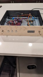
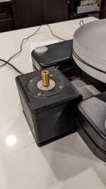
The first want to thank you for the communities help so far. I thought I'd show what I have so far as well as ask a couple questions. Forgive me if some of these are elementary.
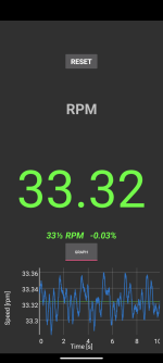
First being it looks like I am getting inconsistent speed throughout the rotation of the platter. Any thoughts on how best to adjust for this? Full screen the first image to see The RPM graph
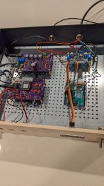
Second being It is my understanding that the I²C interface only works for The two line 16 character LCD and will not work a seven segment display I²C backpack as I am using for the RPM display. If I want to use the same seven segment I will have to adjust the pin out
This is very much still in the works The face plate's going to get changed and I should probably add a fuse...
First being it looks like I am getting inconsistent speed throughout the rotation of the platter. Any thoughts on how best to adjust for this? Full screen the first image to see The RPM graph
Second being It is my understanding that the I²C interface only works for The two line 16 character LCD and will not work a seven segment display I²C backpack as I am using for the RPM display. If I want to use the same seven segment I will have to adjust the pin out
This is very much still in the works The face plate's going to get changed and I should probably add a fuse...
Attachments
Last edited:
What your graph is showing is W & F and the motor controller cannot correct for this. If you are using a smart phone app to measure this by placing the phone on the platter, I would question the accuracy of phone app. An app that uses a 3150Hz test tone on a record will be more accurate. As member rif wrote, small amounts of W & F are usually a mechanical issue not an electrical one.
You cannot use a single display for both motor controller and tachometer readout. The SG4 I2C interface only works with 2x16 LCD displays and only those that use the PCF8574 or PCF8574A interface chip.
You cannot use a single display for both motor controller and tachometer readout. The SG4 I2C interface only works with 2x16 LCD displays and only those that use the PCF8574 or PCF8574A interface chip.
- Home
- Source & Line
- Analogue Source
- DIY 4 Phase Sinewave Generator for Turntable Motor Drive