Replying to my own post above ! My amp is putting out 15.2 volts, not 13.Bill, thanks for pointing me in the right direction, your advice is appreciated. The input side of my output transformers are now wired in series, my voltage divider between the signal generator and the amplifier is dropping the amplifier output to 13volts and my transformers are measuring 100 volts. I'm very happy with that. Thanks again. Rob.
There were more parts than I realized on back order or discontinued. I've updated the Mouser cart so the new link in the OP will now have all of the parts available.I would like to build this but it looks like so many of the items are either back-ordered or discontinued does anybody have an updated bill of material?
I also updated the PCB to Rev C for use with the MCP101-450HI/TO reset controller. The original PCB (Rev A) and the Rev B PCB have the layout for the DS1833 reset controller, the pinout of which is the mirror image of the MCP101-450HI/TO; the MCP101-450HI/TO can be used with the Rev A/B PCBs, but it must be inserted backwards.
The parts distributors are having the same supply issues as the rest of the economy and parts become unavailable constantly. Fortunately, they also stock many of the parts from more than one supplier so if the designated part is unavailable, do a search using the generic or core part number and alternatives can be identified. You must verify that the footprint is the same, as a search will show surface mount as well as through hole versions of the same part. When in doubt, look at the datasheet which is also on line, or the parameters listed in the table view and verify the part dimensions are the same as the originally designated part.
I have not been able to find the OLED expanders with "A" series of PCF8574. Can you point me to the source you used? I've tried google, Amazon and eBay. Thanks.I just received a question that needs clarification: The I²C interface chip for the LCD display must be type PCF-8574A, not PCF-8574. The two chips work nearly the same but have different address schemes; only the PCF-8574A chip will work with the SG-4 firmware change.
The 'A' series chips will have addresses 038h-03fh; the non-series 'A' chips will have addresses 020h-027h on their instruction sheets.
e-Bay has them, but you have to look carefully. This link shows an "A" series chip on one of the close-ups, but you should probably contact them to be sure:
https://www.ebay.com/itm/234062594780?hash=item367f37c2dc:g:KSIAAOSwqARfvBSr
Apparently, these chips are misunderstood by most of the people selling them. They list the default address as 0x20h or 0x38h when in reality, the default address is 0x27h or 0x3fh. Most also are unaware of the differences between the PCF8574 and the PCF8574A which determines the range of addresses (0x20h-0x27h for the former and 0x38h-0x3fh for the latter). I've ordered displays that explicitly showed 0x20h addresses in the description and the photos, but in reality, they have the "A" series interface chip so the address is 0x3fh. That is why you should contact the seller to verify.
I just see Ralph posted about the updated firmware, which solves this dilemma. If you have the older version firmware (v1.04) you will need to source an LCD with an "A" series interface chip; if you have v1.05 firmware, shorting TP1 to ground will allow you to use a non-"A" series interface chip.
Probably easier to send the 4 processor chips to me and I'll reprogram them. email me at billatphoenix-engrdotcom.I have the 1.04 version (4 of them) so I need to find the "A" version of the expander chip. Wish I would have waited a couple weeks to get the 1.05v. Ah well, that's DIY. I' don't suppose it's possible to just swap the PCF 8574 with a PCF8574A chip?
Thanks, I will do so.Probably easier to send the 4 processor chips to me and I'll reprogram them. email me at billatphoenix-engrdotcom.
I'm looking for someone to build a complete unit for me (sg4, ma3d, motor, whatever else there may be). Can someone who has kept up with the latest info help me out? Willing to compensate you of course.
I am embarrassed to say that after an enthusiastic start, I never built one myself, but did start to aquire parts. At this point I cannot pick up where I left off, and am throwing in thr towel. Too much time has passed, the threads are long, and I have other priorities.
Parts wise, I have the motor, pulley adapters, and at least a few ma3d and sg4 boards. I probably have other parts too.
PM me if you're interested.
I just finished the version of the SG4 with OLED display. It is cool. I would like to combine the SG4 with an Arduino-based tachometer in the same case but with a single OLED display. It seem to me that data from the SG4 should be able to be fed to the Arduino and added to the OLED controlled by the Arduino. I would appreciate thoughts on whether or not this is feasible and suggestions for how to make it happen.
Here's a link to thread about the Arduino tachometer. It's lengthy and probably not necessary to read it in order to answer my question.
https://www.diyaudio.com/community/...layer-lcd-display.301609/page-30#post-6927224
Here's a link to thread about the Arduino tachometer. It's lengthy and probably not necessary to read it in order to answer my question.
https://www.diyaudio.com/community/...layer-lcd-display.301609/page-30#post-6927224
This is only relevant to those of us using Papst or other large motors.
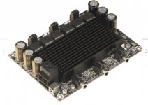
I recently rebuilt my SG4 setup, using 3 x 80VA transformers and a 'Wondon' 3 x 200W class D amplifier. Something I hadn't considered before is the heat at idle that an amp of this size emits. According to the spec sheet the amp is around 90% efficient, and has an idle usage of about 10W. Under normal load, with the large Papst motor the total output is about 45VA, under these conditions the heatsink runs at around 65*C, quite a bit hotter than I like.
There is a built-in 12V fan header, but when this cuts in it is quite noisy, not what I want , so I ended up using an 80mm 12v fan fed by a 6V supply, which runs almost completely silently, and keeps the temp down to around 35*C.
The bottom line is that though it's a good idea to allow some headroom, it is quite easy to go overboard.
I recently rebuilt my SG4 setup, using 3 x 80VA transformers and a 'Wondon' 3 x 200W class D amplifier. Something I hadn't considered before is the heat at idle that an amp of this size emits. According to the spec sheet the amp is around 90% efficient, and has an idle usage of about 10W. Under normal load, with the large Papst motor the total output is about 45VA, under these conditions the heatsink runs at around 65*C, quite a bit hotter than I like.
There is a built-in 12V fan header, but when this cuts in it is quite noisy, not what I want
, so I ended up using an 80mm 12v fan fed by a 6V supply, which runs almost completely silently, and keeps the temp down to around 35*C.The bottom line is that though it's a good idea to allow some headroom, it is quite easy to go overboard.
Attachments
Last edited:
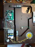
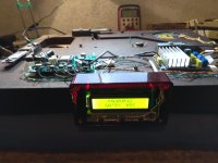
I have completed installation of SG4 into my Thorens TD321 and thought I would share this. It should be applicable to any of the TD300 series turntables. They use a low voltage motor so powering SG4 and the TDA7492 amplifier (ebay) from 12V DC is adequate, the amp drives the motor direct (no step up transformer needed). It was necessary to attenuate the SG4 output otherwise the TDA7492 clips the sine wave output. I set it at max output without clipping with SG4 level at 128, the motor still runs OK with SG4 level at 64 so scope to fine tune.
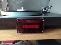
The TD300's uses a 3 way rotary switch to operate 33 - OFF - 45, some head scratching and I realized a rotary brake before make switch with all the ways paralleled might give the momentary switch action to start/stop the motor and another pole on the switch to 45. This works with help of the 2 spare inverter stages in the 74hc14 on the SG4 board. I'll post more info if anyone is interested. SG4 & TDA7492 amp were installed inside the turntable but the solid wood plinth did not allow the display to be inside as well so I put the display inside a clear plastic Hammond box which at moment is stuck on front of tunrtable with double sided foam table. It includes 3 buttons for setting up SG4.
Regards
Colin
Attachments
Seth, I would like to inquire about purchasing a couple of the newest SG4 controller chips. I am not very familiar with actual use of the forum, so hopefully this gets to you. My name is Parris Neal living in Colorado. You can also contact me directly "parris_neal@yahoo.com". Thank you!Seth Hensel
I'm having an odd problem with the SG4. The on-board display, DS1, flickers. The OLED works fine. I replaced U3, 74HC595 and that had no effect. The microprocessor works fine on another board. I don't completely understand the circuit so I could use a suggestion what to try next. Thanks.
- Home
- Source & Line
- Analogue Source
- DIY 4 Phase Sinewave Generator for Turntable Motor Drive