I did not simulate or measure it but having two constant current sources in series it should. There are of cause a lot of other ways to make a current source and the simple BJT-Led variant should be more then good enough.Output impedance of that simpler circuit is already more then 500kOhm. I will build this buffer first simply with resistors as current sources. The current mirrors act as current sources too anyway.
Please correct the emitter connection of the sources in drawing of post 2132.
For each input transistor pair I see two complementary current sources in parallel,
not series. One virtue of this arrangement is that the LEDs are constant current
driven. But the impedance may be reduced because of the inverted operation
of one of the paralleled sources with respect to their output. Please simulate.
Andy, i can not see a mistake. Can you describe more detailed what went wrong ?
OK, i will do a simulation. Maybe you are right. I have not used that arangement so far as constant current sources in an amplifiers. I needed a floating current source to supply a TL341 shunt in a PSU.
I have now build the symmetric Schlotzaur and got it working, just. I made a + - 12V version and used simpy 2kOhm resistors to feed the differential amps. I seems to work best without the emitter resistors. Connected that way i measured 15mA in the output trannies and i think that is fine. Transistors used are 2SA1015 and 2SC1815 with hfe of ca. 200, also in the output. DC stability is very good. I measured only 0.3mV DC offset.
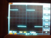
The problem is the tremendoes speed. That thing is damn fast. At my measurement limit of 20MHz i can see no sign of falling response. I starts to triangulate somewhat up there though. At first it oscilated on a stable frequency. The output looked like an assymmetric triangle and the trannies got hot. I then decoupled locally with 110Ohm series resistors and 1000uF Pannasonic FM caps. That was much better but the 100kHz squarewave still had an overshot. I tried all kinds of things like limmiting the input with a 150pF to ground or bootstrapping the output with a 1nF cap from input to output. So far only partly sucessfull. I need a rest.
OK, i will do a simulation. Maybe you are right. I have not used that arangement so far as constant current sources in an amplifiers. I needed a floating current source to supply a TL341 shunt in a PSU.
I have now build the symmetric Schlotzaur and got it working, just. I made a + - 12V version and used simpy 2kOhm resistors to feed the differential amps. I seems to work best without the emitter resistors. Connected that way i measured 15mA in the output trannies and i think that is fine. Transistors used are 2SA1015 and 2SC1815 with hfe of ca. 200, also in the output. DC stability is very good. I measured only 0.3mV DC offset.
The problem is the tremendoes speed. That thing is damn fast. At my measurement limit of 20MHz i can see no sign of falling response. I starts to triangulate somewhat up there though. At first it oscilated on a stable frequency. The output looked like an assymmetric triangle and the trannies got hot. I then decoupled locally with 110Ohm series resistors and 1000uF Pannasonic FM caps. That was much better but the 100kHz squarewave still had an overshot. I tried all kinds of things like limmiting the input with a 150pF to ground or bootstrapping the output with a 1nF cap from input to output. So far only partly sucessfull. I need a rest.
Messing around with the Symmetric Schlotzaur Buffer on the bench is not profitable i thought so i will do some rounds of simulation to get a better grasp of it´s inner workings.
I also will try to simulate the output impedance of the floating current sources.
I put some more thought into the Simple BJT-MOS phonostage. I now spit the feedback resistor in two and included the output cap into the feedback loop. I also lowered the gain of the second stage by 6dB. The feedback cap i made from 6 Wima FKP-2 this time. They have a tolerance of 2.5% so i thought the Self trick of using several in parallel-series could improve tolerance. No luck this time. They measure 6.82nF and should have 6.666_ _ nF. So they are nearly exactly 2.5% too much but very similiar. This is not a big deal. I will adjust the 47kOhm and 500kOhm resistor. I have not tried this circuit because i ran out of 1MOhm resistors. I hope it works. Some may object to the big 1000uF / 16V Panasonic FC elcaps in the signal chain of the input stage. I can only tell you it sounds mighty fine. They are oversized and not much voltage develops over them even in the bass so distortion should be low. You can bypass them with 10nF Polypropylens though.
Attachments
I have now optimised the BJT-MOS phonostage. I established an AC and DC feedback path so i do not split the DC resistor any more. RIAA precission is now + - 0.2dB or better from 200 to 20Khz. - 3dB is at 280kHz and there is still a small lift in the bass with around plus 1dB at 20Hz. I like that so i keep it in. The 1kHz squarewave looks pretty decent. For something so simple i think the performance is very good. This circuit is also nice for experimenting with pre RIAA EQ because the caps that set the EQ carry very little DC voltage over them so clicks and pops when switching should not be a problem. HF balance is trimable anyway. The trimmer could be substituted with a potmeter plus a scale. There are 6 x 10nF anyway so i could imagine a lot of combinations. The caps can be connected in several ways. I have shown two versions. Has anybody an idea what works better or are the connections similar in sound and performance ? What could be improved? Well, the input transistors can be doubled or even quadrupled. I have seen a phonostage from Accuphase that even used 16 pc in parallel. The really low Rbe` ones could be used if you have them. The Led bias to the cascodes could be filtered as i usually always do. Do not expect a miracle. The difference is small and you have two elcaps more that have their own issues. I deliberately did not use current mirrors and current sources. Simplicity was the goal. OK, this circuit will react stronger on the PSU then circuits with more in circuit regulation. That can be a blessing or a curse, depending how you look at it. The elcaps in the signal chain after the cascode can be substituted with foils. Wima makes some really small 10uF MKTs that work well. You need at least 20uF so that the bass will not drop.
Attachments
Andy, i can not see a mistake. Can you describe more detailed what went wrong ?
There is just a small drawing error in the input emitter region - circuit of post 2132.
In the pre stage.. It's the inner cap below the input pair that sets the lower frequency...That cap must be something like 4700 uF..or bigger..then the output's can be 3.3 uF
I would prefer to place a pair of Jfet's in the input (I know the reasons why you didn't) and stack some more Led's to open the cascodes a little more...
For the output I would like some more voltage...Like running the IRF's at +-50 V and with some current... Experience with an IV-converter tells me that they sound better if used like that..
Last edited:
AS, now i see it ! I was a bit tired when i looked at it. Thanks.
MiiB, i just took the caps i had lying around but i think 3.3u at the output of the pre-pre will not do it. That cap sees less then 3kOhm when i am right. Making the resistors higher after the pre-pre will increase the noise. I whould not go higher then 5kOhm in any circumstance. The other option whould be to make the second stage series feedback and the 75usec transimpedance. I have shown a circuit that is DC coupled too. You will find a lot of J-Fet stages in this tread when you look back. If you like i could draw a version that is good and simple Yes, i will make a version with plus - minus 24V. i think plus - minus 50V is a bit of overkill for the second stage but that is posible too. I used only two Leds in the input stage because ideally the collector potential should be at 1/2 the PSU voltage and i spread the remaing 6V between the two transistors. I could use a current mirror here to get more voltage over the input. Then plus - minus 12V is enough i think. I will go back to the drawing board.
MiiB, i just took the caps i had lying around but i think 3.3u at the output of the pre-pre will not do it. That cap sees less then 3kOhm when i am right. Making the resistors higher after the pre-pre will increase the noise. I whould not go higher then 5kOhm in any circumstance. The other option whould be to make the second stage series feedback and the 75usec transimpedance. I have shown a circuit that is DC coupled too. You will find a lot of J-Fet stages in this tread when you look back. If you like i could draw a version that is good and simple Yes, i will make a version with plus - minus 24V. i think plus - minus 50V is a bit of overkill for the second stage but that is posible too. I used only two Leds in the input stage because ideally the collector potential should be at 1/2 the PSU voltage and i spread the remaing 6V between the two transistors. I could use a current mirror here to get more voltage over the input. Then plus - minus 12V is enough i think. I will go back to the drawing board.
MiiB, i just took the caps i had lying around but i think 3.3u at the output of the pre-pre will not do it. That cap sees less then 3kOhm when i am right. board.
In low frequencies it sees rather high impedance.. the base cut off, that happens in the inner Cap...That cap needs to be big...
My take on the same...We're not that far apart...I kept the split Riaa...
I tried to see the distortion by cutting the shaping cap'ed elements out....At 70 dB.. amplification it does look rather well...")
Harmonic Frequency Fourier Normalized Phase Normalized
Number [Hz] Component Component [degree] Phase [deg]
1 1.000e+03 7.739e+00 1.000e+00 179.72° 0.00°
2 2.000e+03 6.470e-04 8.360e-05 -87.46° -267.17°
3 3.000e+03 2.326e-05 3.006e-06 0.10° -179.62°
4 4.000e+03 1.860e-05 2.403e-06 0.03° -179.69°
5 5.000e+03 1.488e-05 1.922e-06 0.03° -179.69°
6 6.000e+03 1.240e-05 1.602e-06 0.02° -179.69°
7 7.000e+03 1.063e-05 1.373e-06 0.02° -179.69°
8 8.000e+03 9.297e-06 1.201e-06 0.01° -179.70°
9 9.000e+03 8.264e-06 1.068e-06 0.01° -179.71°
Total Harmonic Distortion: 0.008376%
I tried to see the distortion by cutting the shaping cap'ed elements out....At 70 dB.. amplification it does look rather well...
Harmonic Frequency Fourier Normalized Phase Normalized
Number [Hz] Component Component [degree] Phase [deg]
1 1.000e+03 7.739e+00 1.000e+00 179.72° 0.00°
2 2.000e+03 6.470e-04 8.360e-05 -87.46° -267.17°
3 3.000e+03 2.326e-05 3.006e-06 0.10° -179.62°
4 4.000e+03 1.860e-05 2.403e-06 0.03° -179.69°
5 5.000e+03 1.488e-05 1.922e-06 0.03° -179.69°
6 6.000e+03 1.240e-05 1.602e-06 0.02° -179.69°
7 7.000e+03 1.063e-05 1.373e-06 0.02° -179.69°
8 8.000e+03 9.297e-06 1.201e-06 0.01° -179.70°
9 9.000e+03 8.264e-06 1.068e-06 0.01° -179.71°
Total Harmonic Distortion: 0.008376%
Attachments
Last edited:
So you degenerated the Fets some more and run that thing on plus-minus 60V !
Good work. As far as i can see you added a soft subsonic filter under 30Hz. Does that come from the 3.3uF after the pre-pre ? Do you think that the 100kHz feedback resistors are correct ? I thought more about 1MOhm.
Good work. As far as i can see you added a soft subsonic filter under 30Hz. Does that come from the 3.3uF after the pre-pre ? Do you think that the 100kHz feedback resistors are correct ? I thought more about 1MOhm.
the fb resistors are 1000 Kohm...
The low cut filtering comes from the caps....my experience with loudspeakers is that when you remove amplitude you can to some degree replace it with phase shift...here the signal is the same level at 20 Hz and 1 Khz, but elevated slightly at 70 Hz app 0,7 db...
btw... We go back a bit, as the LA audio mono blocks are not totally unfamiliar to me...
nice to see you toying with the small electric critters...
Yes, right, it says 1000kOhm. Yes there is a small bump in the deeper regions with the values i choose. I like that slight wamth in my system. I have that LA - Audios since a long time and have updated them a bit. Currently i am working on my own poweramp and it is good to have the LAs as a benchmark. Do we know each other from the old times ?
Long long time ago when i was a bright kid, I worked for Lennart, making the mechanics for LA-audio, we did spend some time together in Berlin for the Funk-ausstellung, you may remember the LA-audio tubed Car amplifier....
then I also have the Raidho acoustics company...
Regarding the PSU...I have made a PCB version of salas shunt.. where the voltage is zener set, that could be changed a bit to be set with JFET..resistors..Also the Riaa deserves a board don't you think...??
then I also have the Raidho acoustics company...
Regarding the PSU...I have made a PCB version of salas shunt.. where the voltage is zener set, that could be changed a bit to be set with JFET..resistors..Also the Riaa deserves a board don't you think...??
Now i can remember you. Great speakers you make ! The invincible Lars the Wiking plays them all the time for me. Yes, let me do the phono PCB and you make the PSU ? That could be fun ! You can do the phono board too if you find the time but i whould like to implement some options like being able to use BJTs in the pre-pre and making provison for more Fets in parallel, just in case.