Fab, have you seen Pavel's thread here? Can you hear a difference between 2 solid state preamps? A difference in sibilance was heard by some people, amongst other things.
The step response as detailed above, 1V step derived from a logic signal, at 200ns/div, the traces are
yellow - signal in
magenta - after non-inverting buffer (sorry, had to edit this line after checking)
blue - after 4 inverts
green - after 8 inverts

Clearly you don't want to enter slew-limiting (and this isn't an issue for normal audio signals of course).
yellow - signal in
magenta - after non-inverting buffer (sorry, had to edit this line after checking)
blue - after 4 inverts
green - after 8 inverts
Clearly you don't want to enter slew-limiting (and this isn't an issue for normal audio signals of course).
Last edited:
Fab, have you seen Pavel's thread here? Can you hear a difference between 2 solid state preamps? A difference in sibilance was heard by some people, amongst other things.
Wow, that thread (in your link) went massively sideways. Anything that ends in that kind of vitriol proves nothing.
Oh, don't worry about the last few posts, it's almost to be expected, there is some interesting stuff in there, I can cut to the chase, as I understood it, if you don't want to bother with it, no problem.
The step response as detailed above, 1V step derived from a logic signal, at 200ns/div, the traces are
Out of curiosity... can you run that one more time on a chain of square waves at about 10khz?
It would be interesting to see the devistation.
Scott, thanks for the link. I had a quick look but after many posts I find it difficult to understand the result....
Anyway peoples may have different abilities in audibility because everybody has a different experience and peoples are more or less paying attention to details....Not to mention the audio gear quality they use for listening...
Fab
Anyway peoples may have different abilities in audibility because everybody has a different experience and peoples are more or less paying attention to details....Not to mention the audio gear quality they use for listening...
Fab
Actually all the variables was one of the most interesting aspects for me including that people perceived differences on quite poor quality setups.
But was it really a blind test or the peoples knew which file they were playing?
Sorry I have not read the whole thread which is very long....
Fab
Sorry I have not read the whole thread which is very long....
Fab
No, it wasn't blind, some people used foobar and did quite well. Proper blind tests can't be done on forums, but schematics, measurements and and audio files were provided and I think it was of value to a number of members. I wouldn't be surprised if some people have done better experiments of their own after participating in the thread.
Fab, have you seen Pavel's thread here? Can you hear a difference between 2 solid state preamps? A difference in sibilance was heard by some people, amongst other things.
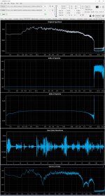
Those two files are synchronized to within one sample time, so I ran up some comparisons using the Python signal library. They are basically identical where it matters, I compared the raw signals, where the difference was clearly due to the slight time offset, and the cross-correlations matched the self-correlations, taken in 1000 sample chunks, and the spectra match (apart from ultrasonic noise floor) again taken in chunks (of 2048 samples). For instance:

This is the same for all the chunks, the ultrasonic noise floor beyond the brick-wall filter is different, but well down, at audible frequencies the spectra sit exactly on top of each other.
Out of curiosity... can you run that one more time on a chain of square waves at about 10khz?
It would be interesting to see the devistation.
Given its a step response over about a microsecond, it won't change whether its 1Hz, 10kHz or 100kHz. BTW the falling edge was very symmetrical to the rising edge which is why I didn't bother posting it as well. To be expected given the repeated inversion.
Given its a step response over about a microsecond, it won't change whether its 1Hz, 10kHz or 100kHz. BTW the falling edge was very symmetrical to the rising edge which is why I didn't bother posting it as well. To be expected given the repeated inversion.
I agree it was to be expected, it's the falling edge I wanted a look at. If it's the same then it all makes sense.
Thanks.
Interesting test. What happens to transients such as a step response square wave, etc? Phase? Ringing/overshoot effects.
On Focusrite Solo, you should be able to get a -130dB noise floor with a -10dB peak signal for a 120dB SNR. What is a standard 1kHz signal harmonic distortion FFT look like?
On Focusrite Solo, you should be able to get a -130dB noise floor with a -10dB peak signal for a 120dB SNR. What is a standard 1kHz signal harmonic distortion FFT look like?
The step response as detailed above, 1V step derived from a logic signal, at 200ns/div, the traces are
yellow - signal in
magenta - after non-inverting buffer (sorry, had to edit this line after checking)
blue - after 4 inverts
green - after 8 inverts
Clearly you don't want to enter slew-limiting (and this isn't an issue for normal audio signals of course).
I don't think there is any slew limiting visible here. Just some mild overshoot and limited risetime.
You have to up the signal significantly to see slew limiting.
And it probably will be just the 1st stage that shows it, the signal being slower after the 1st stage.
Jan
Last edited:
I would had set the input impedances to 10 k (usually used in audio lines), to set at least two X10 gain stages, one inverting, one non inverting, with the 20dB attenuator before them.I realize in retrospect I should have made jumpers on the board to allow more stages to be non-inverting and thus subject to common-mode distortion, not just the first buffer, as that would be an interesting comparison.
I would also have added, on each IC, the place for a compensation cap and IC supports to be able to evaluate more than one model of integrated circuit.
About slew rate, if the first OPA is the slower one, there is no reason of further limitation. To put all chances on your side to reveal distortions due to them, try to put the circuit in order to have (with VFAs), the fastest first.
The result of listening test should not lead to definitive conclusions if the listening channel (source + playback system) is the limiting factor.
Last edited:
I'm also convinced that NE5532's/5534's are very fine audio opamps that still can successfully compete with more recent parts.
I'd be interested, though, how a chain of twelve would perform in non-inverting mode.
Best regards!
I'd be interested, though, how a chain of twelve would perform in non-inverting mode.
Best regards!
I don't understand----if significantly slowing the rise time of an input signal isn't slew limiting, then what is?I don't think there is any slew limiting visible here.
DeltaWave Audio Null Comparator gives:at audible frequencies the spectra sit exactly on top of each other.
enjoy.
Ulli
Attachments
Last edited:
I would had set the input impedances to 10 k (usually used in audio lines), to set at least two X10 gain stages, one inverting, one non inverting, with the 20dB attenuator before them.
I would also have added, on each IC, the place for a compensation cap and IC supports to be able to evaluate more than one model of integrated circuit.
About slew rate, if the first OPA is the slower one, there is no reason of further limitation. To put all chances on your side to reveal distortions due to them, try to put the circuit in order to have (with VFAs), the fastest first.
The result of listening test should not lead to definitive conclusions if the listening channel (source + playback system) is the limiting factor.
Yes it would be nice to generalize the board. I'm thinking you want to investigate several regimes:
1) unity gain follower - highest common-mode voltages.
2) approx x10 gain non-inverting stage (alternating with attenuation to keep levels fixed). Low common-mode swing, but probes the performance with 20dB lower loop gain.
3) inverting unity gain (like it is currently), should be best performing
Interesting tool by the look of it.
- Home
- Source & Line
- Analog Line Level
- 12 opamps chained - measurements