I don't understand----if significantly slowing the rise time of an input signal isn't slew limiting, then what is?
Its the difference between rise time and slew rate. Slew rate happens with large signals and causes a straight line up (or down). What you say there was an exponential rise, which is typical for an RC time constant slowing down the rise, but without the massive distortion that slew rate limiting causes. In other words, rise time limiting does not cause harmonic distortion. Slew rate limiting does.
There's some Wikipedia entries explaining the difference.
Jan
Rise time is linked to small-signal bandwidth. That's always the same regardless of signal amplitude. Slew rate imposes an additional constraint on the rate of voltage change in time domain, effectively limiting large signal bandwidth.
At low amplitudes, you have plenty of slew rate even for a relatively high-frequency signal. Increase the amplitude, and at some point the required maximum rate of voltage change will exceed amplifier slew rate, which obviously can't happen. Excessive distortion may be observed well below that point, with some differences between BJT and FET input parts (basically, FET input slew rate tends to be worth less than BJT input slew rate).
I wonder how the kink at the beginning of the magenta curve came about. Did the part frantically start slewing only to remember its finite small-signal bandwidth at some point? I wouldn't be surprised if the 5532's nested feedback architecture came into play here.
Last edited:

Agreed.Yes it would be nice to generalize the board. I'm thinking you want to investigate several regimes:
1) unity gain follower - highest common-mode voltages.
2) approx x10 gain non-inverting stage (alternating with attenuation to keep levels fixed). Low common-mode swing, but probes the performance with 20dB lower loop gain.
3) inverting unity gain (like it is currently), should be best performing
Something you could do with your current board is to alternate +20dB inverting stages with -20dB inverters (involves just resistor changes).
Why would you want to do that? Because the output impedance is neither finite nor linear, and you could see artifacts, in particular phase-related ones and at some frequency the -20dB inverting stage could become mildly non-inverting.
That would need to be compared with other types of opamps: I suspect that "weaker" opamps like the TLO72 would do much worse in this test, so seeing "something" with the NE5532's would not mean they are bad.
Interesting test. What happens to transients such as a step response square wave, etc? Phase? Ringing/overshoot effects.
On Focusrite Solo, you should be able to get a -130dB noise floor with a -10dB peak signal for a 120dB SNR. What is a standard 1kHz signal harmonic distortion FFT look like?
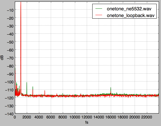
I get, with about 450mV rms level:
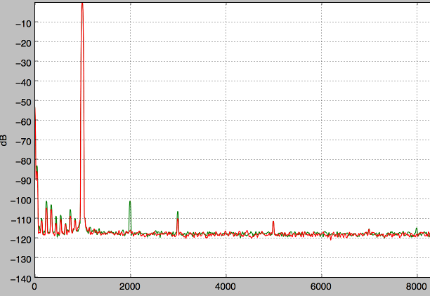
And zoomed in:
So mainly 2nd harmonic, < 0.001% through 12 opamps. The Focusrite uses the CS4272 IIRC, which clearly has good symmetry as the loopback is devoid of even harmonics.
Note these plots are spectrums, not spectral density plots, so the noise floor isn't independent of sample rate or window function.
And just for fun I made a divider using 1k+220nF(film) : 100nF (ceramic), and got this:

Watch out for those non-NP0 ceramics!
Watch out for those non-NP0 ceramics!
I did a similar but less rigorous test where I ran the audio signal through ten 5532s and switched between them and a wire. Nobody could hear any difference.
As far as switching op amps, that's not always so straightforward. I prototype everything I possibly can with 5532s. They're very forgiving. They respond to better decoupling but won't fall apart with marginal decoupling. I've never had any problems with oscillation when used in filter circuits. I've never had any problems with the 5532 at all that I can recall.
It is my custom to use the 2134 when I want to reduce output offset, especially in adjustable circuits where the offset varies with potentiometer setting. When I was prototyping my buffered volume/balance/voltage amplifier modular board, I built it with 5532s. It worked great and sounded excellent, but the output offset varied from around 3 mV to over 20 mV when the volume control was rotated. The offset even went negative during the rotation. I wanted to mitigate this so I popped a 2134 into the output buffer circuit. To my surprise it oscillated when I turned the volume control to zero. It wouldn't stop oscillating until I disconnected the power. I added a small ceramic capacitor between the output and inverting input and a resistor in series with the non inverting input. Problem solved, works and sounds great. Plus the 5532 has a little less offset drift when popped into the modified circuit, thanks to the resistor in series with the input.
Last edited:
You didn't say how much the output offset was with the 2134. Interesting, because the datasheet quotes for offset voltage on both the 5532 and 2134 are 0.5mV.It is my custom to use the 2134 when I want to reduce output offset, especially in adjustable circuits where the offset varies with potentiometer setting. When I was prototyping my buffered volume/balance/voltage amplifier modular board, I built it with 5532s. It worked great and sounded excellent, but the output offset varied from around 3 mV to over 20 mV when the volume control was rotated. The offset even went negative during the rotation. I wanted to mitigate this so I popped a 2134 into the output buffer circuit. To my surprise it oscillated when I turned the volume control to zero. It wouldn't stop oscillating until I disconnected the power. I added a small ceramic capacitor between the output and inverting input and a resistor in series with the non inverting input. Problem solved, works and sounds great. Plus the 5532 has a little less offset drift when popped into the modified circuit, thanks to the resistor in series with the input.
Of course, the other factor is cost----the 2134s have gone through the roof, and are almost $5 apiece, whilst the venerable 5532 is only $1!!!!
Yes but the 5532 is a bipolar opamp so has input currents. If you use it with largish & unequal source impedances, those input currents (which are not equal either) will generate extra offset.
The 2134, being a FET input opamp, will not show this.
Jan
The 2134, being a FET input opamp, will not show this.
Jan
You didn't say how much the output offset was with the 2134.
If I remember correctly, it was around 2 mV max, or a factor of ten better.
That's with the bias currents flowing through equal value resistors, like an instrumentation circuit.Interesting, because the datasheet quotes for offset voltage on both the 5532 and 2134 are 0.5mV.
If you design audio circuits with op amps, then you know that it's usually not convenient to DC optimize a circuit. For example, in my circuit the DC bias current for the non inverting input flows through the volume control potentiomenter, which varies between 0 and 100K ohms. It's not only not ideal DC balance but it varies. A typical analog active bass control suffers from the same shortcoming. (You should always have another resistor in parallel with the pot wiper as a "fail-safe" precaution. It should be about 10x the potentiometer value. Sometimes you can get away with less; my volume control as a 220K resistor in parallel with the wiper.)
Less input bias current = less offset for a given value of resistor. Using larger value resistors gives higher offsets. That's how the 2134 reduces offset in a typical circuit; it has lower input bias currents so it develops lower voltage across a given value bias resistor.
Last edited:
For this reason, you are not going to find very many commercial designs employing a bipolar opamp without a coupling capacitor and extra bias resistor. Likewise, the resistor in series with the wiper is generally present as well.Yes but the 5532 is a bipolar opamp so has input currents. If you use it with largish & unequal source impedances, those input currents (which are not equal either) will generate extra offset.
The 2134, being a FET input opamp, will not show this.
For this reason, you are not going to find very many commercial designs employing a bipolar opamp without a coupling capacitor and extra bias resistor. Likewise, the resistor in series with the wiper is generally present as well.
A too large coupling capacitor can create audible thumps and even scratchiness if it's too big, when used in conjunction with a potentiometer.
If you want to DC cascade as many stages as possible, then you have to pay attention to a lot of extra detail. DC cascaded stages can go nuts with too much offset or offset drift.
Then... don't use one that is too big? We are generally talking something like 10 µF (max) of good-quality industrial cap (low leakage) with ample voltage rating. Besides, this should be mostly an issue for single supply circuits, in one as discussed your biggest concern may be keeping the cap from dying within one generation.A too large coupling capacitor can create audible thumps and even scratchiness if it's too big, when used in conjunction with a potentiometer.
There was I thinking I'd invented something novel 🙂I did a similar but less rigorous test where I ran the audio signal through ten 5532s and switched between them and a wire. Nobody could hear any difference.
Douglas Self says lack of decoupling in NE5532/4's leads to no discernable oscillation outside the chip visible to a 'scope, but does create a step increase in THD indicating something internal to the die. Perhaps worth investigating with a SA on the supply rails and a switchable decoupling cap.As far as switching op amps, that's not always so straightforward. I prototype everything I possibly can with 5532s. They're very forgiving. They respond to better decoupling but won't fall apart with marginal decoupling. I've never had any problems with oscillation when used in filter circuits. I've never had any problems with the 5532 at all that I can recall.
Then... don't use one that is too big? We are generally talking something like 10 µF (max) of good-quality industrial cap (low leakage) with ample voltage rating. Besides, this should be mostly an issue for single supply circuits, in one as discussed your biggest concern may be keeping the cap from dying within one generation.
I don't use a capacitor unless I'm using a single supply circuit, which I rarely use. I try to place capacitors at them input and output only if possible. That's why I try to control offset.
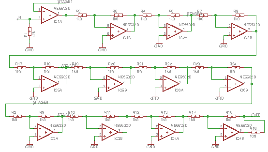
Just reviving the thread as I did another few measurements on the 12 opamp chain (to save people going back, this is the circuit:
And have a THD value using Scarlett Solo v3 and some Python scripting/graphing:
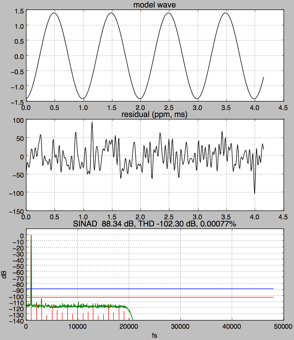
The top trace is the inferred fundamental (done by iterative fitting of a model sinusoid to the data), the second trace is the residual (low pass filtered to 20kHz, units are parts-per-million), and the third shows the measured harmonics as red spikes, the background noise (green) and calculates THD and SINAD.
I still haven't made a similar board for non-inverting stages which I think would be more revealing (show common-mode distortion), but still 0.00077% after 12 vanilla TI branded SMT '5532 stages is impressive as 3rd harmonic distortion will build cumulatively, suggesting the per-stage distortion at sub-ppm levels 0.000064% (there may be some cancellation of even harmonic distortion of course).
I should say the loopback measurement I get for the Solo is 0.00044% which really means the NE5532 board is somewhere from 0.00033 to 0.00121% if the baseline distortion reinforces or cancels the opamps.
And have a THD value using Scarlett Solo v3 and some Python scripting/graphing:
The top trace is the inferred fundamental (done by iterative fitting of a model sinusoid to the data), the second trace is the residual (low pass filtered to 20kHz, units are parts-per-million), and the third shows the measured harmonics as red spikes, the background noise (green) and calculates THD and SINAD.
I still haven't made a similar board for non-inverting stages which I think would be more revealing (show common-mode distortion), but still 0.00077% after 12 vanilla TI branded SMT '5532 stages is impressive as 3rd harmonic distortion will build cumulatively, suggesting the per-stage distortion at sub-ppm levels 0.000064% (there may be some cancellation of even harmonic distortion of course).
I should say the loopback measurement I get for the Solo is 0.00044% which really means the NE5532 board is somewhere from 0.00033 to 0.00121% if the baseline distortion reinforces or cancels the opamps.
And there are punters who are quick to roll these out and swap them for newer parts. 🙄
I've always been a fan of the 5534 and 5532.
I've always been a fan of the 5534 and 5532.
One thing puzzles me in tests such as these and its this...
Manufacturers of high performance opamps often give distortion figures magnitudes more than the levels these kind of test set ups (in this thread) show. Not only that, but the manufacturers (who it must be assumed have absolutely state of the art measuring techniques and equipment) also state that the performance of the opamp exceeds currently availbale measuring equipment.
A typical statement from a data sheet would be:
The special test circuit referred to is the trick of increasing noise gain by the addition of a single resistor per stage.
So I'm always a bit sceptical when I come across seemingly phenomenal distortion performance (as measured) in set ups such as we are discussing in this thread.
When the manufacturers say its difficult and beyond current test equipment set ups when used conventionally how can we come up with such seemingly amazing results in a diy setting.
I haven't the answers and haven't the knowledge to argue the case one way or the other but it is something that consistently puzzles me.
Manufacturers of high performance opamps often give distortion figures magnitudes more than the levels these kind of test set ups (in this thread) show. Not only that, but the manufacturers (who it must be assumed have absolutely state of the art measuring techniques and equipment) also state that the performance of the opamp exceeds currently availbale measuring equipment.
A typical statement from a data sheet would be:
is below the measurement limit of virtually all commercially available equipment. A special test circuit, however, can be used to extend the
measurement capabilities....
The special test circuit referred to is the trick of increasing noise gain by the addition of a single resistor per stage.
So I'm always a bit sceptical when I come across seemingly phenomenal distortion performance (as measured) in set ups such as we are discussing in this thread.
When the manufacturers say its difficult and beyond current test equipment set ups when used conventionally how can we come up with such seemingly amazing results in a diy setting.
I haven't the answers and haven't the knowledge to argue the case one way or the other but it is something that consistently puzzles me.
Distortion depends on frequency, amplitude, and whether its inverting or non-inverting, and the circuit's gain, so you have to expect that unless you match the testing circuit and conditions you'll see a different result. Inverting topology has the advantage that the inputs don't swing, removing (input) common-mode issues completely.
The really high performance chips tend to have a lot more gain to linearize with, 130+dB isn't unknown for instance. Basically if you can make that stable, the error voltage is driven correspondingly lower and only the passives matter really. Negative feedback turns raw gain into precision. More raw gain, more precision, if all else is equal.
The special test circuit thing is just the trick for varying the noise gain independently of the closed loop gain - its sort of like artificially reducing the open loop gain - a small value resistor goes between the two inputs. The noise gain is what the opamp sees, the closed loop gain is what the external circuit sees.
Last edited:
Thanks Mark... I get what you say in the first paragraph... but its when results such as in this thread are light years ahead of other studies and info in data sheets that I start wondering.
Samuel Groners epic text on opamp distortion shows the 5532 distortion worsening markedly at lower load impedances. Your driving just under 1k for most of your opamps and yet your results are spectacular.
I remain a sceptic 🙂
Samuel Groners epic text on opamp distortion shows the 5532 distortion worsening markedly at lower load impedances. Your driving just under 1k for most of your opamps and yet your results are spectacular.
I remain a sceptic 🙂
- Home
- Source & Line
- Analog Line Level
- 12 opamps chained - measurements