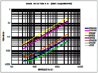
More measurements, this time on a single NE5532, both Signetics variant and TI, with inverting and also follower configurations, like this:

Although in reality its one dual opamp chip so only one set of supply pins!
I plotted distortion against level for 4 combinations, the left hand plots are Signetics, right hand are TI.
The top plots are non-inverting (follower), and the bottom plots are inverting (all unity gain as shown above).

Clearly they show excellent performance although the TI does less well for the follower circuit (common mode issues perhaps?) - can we relate the TI performance here to the 12-opamp series performance - haven't tried yet...
Bit of an eye-opener that we almost get 1ppm level of distortion for the Signetics version, despite the Signetics datasheet saying nothing about the distortion performance at all...
And now the same tests with the 100nF decoupling capacitor omitted - this is why you should never roll opamps blindly, the performance goes to abyssmal very quickly if you don't understand things like decoupling, drive level, bias current etc:

Remarkably the TI chip does slightly better for the follower with no decoupling! The low impedance drive to the chip seems to stop the onset of oscillation for this mode and this chip, but all the others show HF oscillations are killing the performance, especially at higher levels - anyone who's played with designing amps knows oscillation onset at higher levels is a common problem, and its definitely the case for the NE5532 without its 100nF ceramic decoupling...
Although in reality its one dual opamp chip so only one set of supply pins!
I plotted distortion against level for 4 combinations, the left hand plots are Signetics, right hand are TI.
The top plots are non-inverting (follower), and the bottom plots are inverting (all unity gain as shown above).
Clearly they show excellent performance although the TI does less well for the follower circuit (common mode issues perhaps?) - can we relate the TI performance here to the 12-opamp series performance - haven't tried yet...
Bit of an eye-opener that we almost get 1ppm level of distortion for the Signetics version, despite the Signetics datasheet saying nothing about the distortion performance at all...
And now the same tests with the 100nF decoupling capacitor omitted - this is why you should never roll opamps blindly, the performance goes to abyssmal very quickly if you don't understand things like decoupling, drive level, bias current etc:
Remarkably the TI chip does slightly better for the follower with no decoupling! The low impedance drive to the chip seems to stop the onset of oscillation for this mode and this chip, but all the others show HF oscillations are killing the performance, especially at higher levels - anyone who's played with designing amps knows oscillation onset at higher levels is a common problem, and its definitely the case for the NE5532 without its 100nF ceramic decoupling...
BTW I've just realized something very pertinent to this idea of testing opamps in series with inverting configuration - the even harmonic distortion will cancel out between successive stages, so the net amount of even harmonics after 11 inverters is probably about the same as one inverter.
Odd harmonics don't cancel like this and will accumulate 11-fold presumably, or rather 12-fold with the initial follower contributing too.
Think its time to start adding distortion-multiplier resistors to my test setup...
Odd harmonics don't cancel like this and will accumulate 11-fold presumably, or rather 12-fold with the initial follower contributing too.
Think its time to start adding distortion-multiplier resistors to my test setup...
A more sensitive setup would be to attenuate the signal by (say) 40dB and then have one op-amp amplify by 40dB. This could also be done with 60dB or 80dB.
Ed
Ed
BTW I've just realized something very pertinent to this idea of testing opamps in series with inverting configuration - the even harmonic distortion will cancel out between successive stages, so the net amount of even harmonics after 11 inverters is probably about the same as one inverter.
Odd harmonics don't cancel like this and will accumulate 11-fold presumably, or rather 12-fold with the initial follower contributing too.
Think its time to start adding distortion-multiplier resistors to my test setup...
I wrote that in posts #130 and #132, about two years ago...
Ah, I searched for "even" in the first few pages and then gave up!! Yes, and I think those even harmonics would mainly be due to O.S. asymmetry, so how repeatable that is from device to device is unknown to me, but I believe its quasi-comp outputs so probably is pretty repeatable and thus cancels well.
I noticed this happening decades ago, but never had a clear description.BTW I've just realized something very pertinent to this idea of testing opamps in series with inverting configuration - the even harmonic distortion will cancel out between successive stages, so the net amount of even harmonics after 11 inverters is probably about the same as one inverter.
Odd harmonics don't cancel like this and will accumulate 11-fold presumably, or rather 12-fold with the initial follower contributing too.
Well that's not really what I was looking at, since that would seldom be done in real analog signal chains, where the goal is often to trade off headroom and noise and distortion - a +40dB gain stage will have more distortion than two +20dB stages strung together.A more sensitive setup would be to attenuate the signal by (say) 40dB and then have one op-amp amplify by 40dB. This could also be done with 60dB or 80dB.
Ed
Besides that might just swamp the distortion with the noise floor.
There's a neat trick adding a resistor between inverting and non-inverting inputs to increase the noise gain but not signal gain and thus multiply the distortion to be able to measure it - however it didn't seem to work for me when I tried it somehow, the distortion remained stubbornly low!
By the way I'm a bit late answering this as I've been somewhat indeposed for a while.
40dB is a typical gain for a MM phono pre-amp.
The problem with the resistor between the inverting and non-inverting inputs is that its value depends on the open-loop gain, and would typically be less than 1 ohm. The 40dB attenuator followed by 40dB of gain should produce reliable results.
Ed
The problem with the resistor between the inverting and non-inverting inputs is that its value depends on the open-loop gain, and would typically be less than 1 ohm. The 40dB attenuator followed by 40dB of gain should produce reliable results.
Ed
I said above:

(original Signetics NE5534A, follower, and if my calculations are right the red trace is raised 60dB and the purple 40dB above normal (green, probably limited by the QA403)).
I presume you could adapt the technique to any amp with an input pair to help measure very low distortions.
But I've figured out the problem - I was driving the non-inverting input from low-impedance, and that seems to break this trick - adding a series resistance to the source allows the resistor between the inputs to work - it needs to be smaller than both impedances already present on the inputs I think (I've yet to do the maths properly). So now by adding various values of resistance I can artificially raise the noise and distortion to make them more easily measured:There's a neat trick adding a resistor between inverting and non-inverting inputs to increase the noise gain but not signal gain and thus multiply the distortion to be able to measure it - however it didn't seem to work for me when I tried it somehow, the distortion remained stubbornly low!
(original Signetics NE5534A, follower, and if my calculations are right the red trace is raised 60dB and the purple 40dB above normal (green, probably limited by the QA403)).
I presume you could adapt the technique to any amp with an input pair to help measure very low distortions.
Section 3.1 I think? I tried that circuit and wasn't seeing the effect unless I added source resistance of the same magnitude as the feedback resistor....
Yes, section 3.1 for non-inverting, and section 3.2 for inverting.
https://www.ti.com/lit/an/sboa580/sboa580.pdf?ts=1703224649870
https://www.ti.com/lit/an/sboa580/sboa580.pdf?ts=1703224649870
Interesting.Section 3.1 I think? I tried that circuit and wasn't seeing the effect unless I added source resistance of the same magnitude as the feedback resistor....
In the National Semiconductor application note 1671, written by Bob Pease, a small resistor is included, but according to the gain formula, it should not make a major difference.
Section 3.1 I think? I tried that circuit and wasn't seeing the effect unless I added source resistance of the same magnitude as the feedback resistor....
Yes, section 3.1 for non-inverting, and section 3.2 for inverting.
https://www.ti.com/lit/an/sboa580/sboa580.pdf?ts=1703224649870
I believe that the distortion for the common-mode input in a non-inverting configuration is not reflected in the measurements in Section 3.1 because there are many components that are not improved by feedback (equivalently, the input signal is distorted).
For example, a value measured with an input signal of 5V, a signal gain of 1x, and a noise gain of 100x is calculated by multiplying by 1/100. However, if a 5V signal is applied to a circuit with G = +1, its distortion component will remain at its original value.
It seems that the 5532 itself is designed to cancel out common-mode second-order distortion.BTW I've just realized something very pertinent to this idea of testing opamps in series with inverting configuration - the even harmonic distortion will cancel out between successive stages, so the net amount of even harmonics after 11 inverters is probably about the same as one inverter.
Odd harmonics don't cancel like this and will accumulate 11-fold presumably, or rather 12-fold with the initial follower contributing too.
Think its time to start adding distortion-multiplier resistors to my test setup...
Generally, the main component of common-mode input distortion is 2nd distortion, but Toru Kuroda, a famous Japanese DIY writer, noticed that the 5532's distortion was low and the main component was 3rd HD, and the DIY magazine "Radio Technology" wrote the following.
"By matching the collector-to-substrate capacitance of the input protection diode (actually a diode-connected transistor) to the base-to-collector capacitance of the IPS LTP NPN, as the voltage on one increases (the junction capacitance decreases) on the other voltage is reduced (junction capacitance is increased) and skillfully cancels out the 2nd HD."
After reading the article, I confirmed it too.
G=+1 (Rf=0), Rs=10kΩ, f=20kHz, 5Vrms, Vs=±15V
| NE5532 (TI old 1980') 0.0031% | NJM5532 (JRC) 0.0044% | RC5532(FC or Raytheon?) 0.0026% |
| NE5532 (Signe) 0.0019% | NE5532(TI new) 0.0026% | TI old, TI new, JRC, RC, Signe |
It seems that cancellation is not working well with TI's. But the value is lower than NJM.
In that respect, the original manufacturer's signature is a beautiful 3rd HD.
Naturally, making the supply voltage asymmetric increases the 2nd HD.
As far as I have investigated, it seems that AD797 performs similar cancellation.
AD797 0.00179%
This function is effective when the signal source impedance is high and the input signal is large (that is, the gain is small), but the AD797 is not suitable for such conditions at all.
Attachments
Ah, I've figured out - I goofed, the feedback resistor wasn't 2k2 as I thought (all the other resistors on the breadboard were), it was 50 ohms(!). Changing it to 2k2 and there's no need for the 2k2 on the input! By the way the distortion multiplying resistors were 22R and 2R2 for the 40dB and 60dB factors. Removing the input 2k2 lowers the noise for the plain non-inverting response, curves are now:Interesting.
In the National Semiconductor application note 1671, written by Bob Pease, a small resistor is included, but according to the gain formula, it should not make a major difference.
What is the test frequency? I am adding 40dB to the green curve and getting an open-loop THD of 10%.
Ed
Ed
I want the maximum distortion before clipping (0.1% for the 60dB curve). The frequency of 1KHz means that the open-loop gain is 80dB and that I should add 20dB. This gives 1% open-loop THD.
Ed
Ed
- Home
- Source & Line
- Analog Line Level
- 12 opamps chained - measurements
