
Darth Sidious voice "ON"....... dunno, didn't tried and will I .........
"Do it!!!"
Darth Sidious voice "OFF"
Regarding plethora of variations... Anyone familiar with Ben10 cartoon?
😀
Attachments


3.43V, 3.5V and 4.45Vif you test those SJDP with 1A8@24Vdc and write what's Ugs, I can tell ya level shifting resistor with few ohms margin
in fact, have enough time , before hopping to mu Mighty 'Talian Vehicle ...... no need for "I'll be back"
Iq of level shifting thingie is 0V65/22R= 29.5mA
source of IRF510 is approx at 0V level
so, with level shifting resistor we need to push down SJDP gate for its Ugs
say it's 3V5
so level shifting resistor need to be 3V5/29.5mA=118R
take 120R standard value as closest one
Iq of level shifting thingie is 0V65/22R= 29.5mA
source of IRF510 is approx at 0V level
so, with level shifting resistor we need to push down SJDP gate for its Ugs
say it's 3V5
so level shifting resistor need to be 3V5/29.5mA=118R
take 120R standard value as closest one
Is the calculation for Iq taken from the lower rail and that's where we get the 0V65 and 22R from and then we want the current going through the upper half to match current through lower half so that's why we use 29.5mA in our calculation of level shift resistor? This is the assumption I'm going with here and I see where the 22R comes in but how did you come up with the 650mV?
🤔
🤔
0V65 is constant made by Nature (being Mighty by default)
29.5mA is value chosen by Mighty ZM
see "Constant current source with thermal compensation" and https://www.diyaudio.com/community/threads/williams-ring-of-two-current-source.343904/
29.5mA is value chosen by Mighty ZM
see "Constant current source with thermal compensation" and https://www.diyaudio.com/community/threads/williams-ring-of-two-current-source.343904/
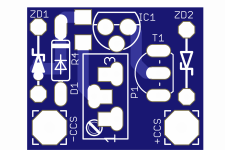
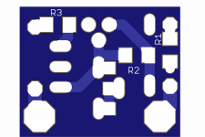
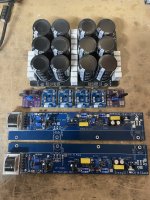
last bling, precision CCS moved to separate Daughterboard
Attachments


Is the startup procedure the same as SissySIT R3 except for CCS P1? Is below correct?
P102 (P202) – irrelevant (Input stage DC offset)
P101 (P201) - set to max; confirm with ohmmeter across R104 - in vicinity of 28R (Input stage bias)
P103 (P203) -irrelevant (OS DC offset)
CCS P1 - set to min ; confirm with ohmmeter - improvise where to put probes (OS Bias current)
P102 (P202) – irrelevant (Input stage DC offset)
P101 (P201) - set to max; confirm with ohmmeter across R104 - in vicinity of 28R (Input stage bias)
P103 (P203) -irrelevant (OS DC offset)
CCS P1 - set to min ; confirm with ohmmeter - improvise where to put probes (OS Bias current)
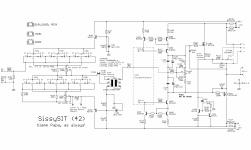
SissySIT 42 with Tokin THF51 SIT with the CCS daughter board.
Or is there a startup procedure for the 42? I looked at the R3 version which looked close to the R1 version I built. I'm printing schematics, build notes, and a checkout/test sheet to use on the bench. I want to keep the magic smoke inside.
Or is there a startup procedure for the 42? I looked at the R3 version which looked close to the R1 version I built. I'm printing schematics, build notes, and a checkout/test sheet to use on the bench. I want to keep the magic smoke inside.
lookielookie
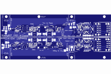
(42) sch with Daughterboard CCS
trimpots initial setting:
P101 at max, confirm measuring across R104
P102 whatever, you'll set it later to have 0mV DC offset at B pin of JP101, ref to GND; only then put jumper on JP101
P103 whatever, you'll set it later to have 0mV DC offset at loudspeaker output of amp, ref to GND
P1 at CCS Daugterboard - turn it fully CCW, on main pcb you have written "CW +Iq"
take care to have 4-5mm clearance between main pcb and daughterboard; I've sent convenient solid core wire for soldering studs
starting/setting procedure pretty much being the same as any SissySIT , taking care of designations above - one DVM at output, one DVM across 0R11 in rail
offset shoot for 0
Iq shoot for 198mV across 0R11 if you want 1A8, for less calc, do not go bellow 1A5 - SissySIT is Special Beast
Attachments


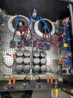
Chassis arrives Monday. I should have a Tokin based SissySIT 42 cooking on the bench sometime next week!
don't need isolators for those solo transistors, just on cascode BDs, sharing same heatsink
Isolators are habit, I was on autopilot.
Cinemags appear to be opposite. I think I followed the markings on the silk. Do they look right to you?
Cinemags appear to be opposite. I think I followed the markings on the silk. Do they look right to you?
autoformer ...........raster pin1-pin2 is smaller than rest of pins are having, and you have each set of pads marked (C, J, E), so if you didn't force it, xformer is OK
ignore label orientation - it can be random placed
and , for both channels pin 1 is to front (narrow side)
ignore label orientation - it can be random placed
and , for both channels pin 1 is to front (narrow side)
At least one of a few things is true...
I find #1 most probable. However, it is interesting. I'll ask Dave if it's supposed to be standard. There's an upcoming build guide brewing where that little tidbit of information would be very helpful. The only place I see a part marking on the datasheet (linked below) is on page 5. None of the 20 I just looked at had the marking on the side with pins 7-12, but that's how it's shown on the data sheet; and how the piece on your 'bottom' board might be.
https://cinemag.biz/output/PDF/CMOQ-4.pdf
🤷♂️
Edit - ZM is always faster and more concise.
- Your two Cinemags are marked differently. If so, no biggie. Pins 1 and 2 are closest together and only fit in the PCB in one orientation. On a "typical" ZM multi-transformer layout, the hole for pin C1 would be in the upper left corner and share a pad with E8. It's hard to tell in the picture, but all the visible pins look evenly spaced, which leads me to believe that you have them oriented properly.
Of the 400 or so CMOQ-4HPCs I have purchased, I didn't really look at all of them. However, I just pulled out 20 for curiosity. Pin one is closest to the C in 4HPC for all of them, and they most closely match the one on your 'top' board.
- One of your two Cinemags is wound improperly.
- ZM ooked the silkscreen.
- ZM ooked one of the board layouts and/or deviated from his 'standard' multi-transformer layout..
I find #1 most probable. However, it is interesting. I'll ask Dave if it's supposed to be standard. There's an upcoming build guide brewing where that little tidbit of information would be very helpful. The only place I see a part marking on the datasheet (linked below) is on page 5. None of the 20 I just looked at had the marking on the side with pins 7-12, but that's how it's shown on the data sheet; and how the piece on your 'bottom' board might be.
https://cinemag.biz/output/PDF/CMOQ-4.pdf
🤷♂️
Edit - ZM is always faster and more concise.
ZM - I need your help.
4U400 - Tokin THF51S on SissySIT 42 boards
Per channel: Antek 300VA 18+18 donuts
IEC main fuse and 2.5A fuse per channel
I started the procedure to get the first channel going.
Pots set according to procedure:
P101 MAX
CCS P1 MIN
Others - as-is (middle-ish)
jumpers open
meters in place.
Rails unloaded appx 25.5V
Power up, I was expecting low volts reading across 0R22. "dodo" = "zero" in this case, right? I did NOT see zero... I saw ~400mV.
I turned the CCS Pot and the lowest I could go is ~270mV. To double-check I looked at the rail wires with a clamp ammeter and saw 2.5xA on positive and negative rails.
Power down - contact ZM...
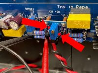
My CCS P1 measuring procedure
When I measured CCS P1 I was going from T1 leg to R104. See the dots on the picture.
At first it was ~500R (as expected). I checked other side of R104 and saw 1K5 (as expected)
I turned it to get 0R from T1 to R104.
Current status:
No smoke is released.
No fuses blown.
MOSFET heatsink was heating up quicker than SIT heatsink.
Can't get current into range. I simply can't get current down to 1.6A range for cooking.
Advice?
4U400 - Tokin THF51S on SissySIT 42 boards
Per channel: Antek 300VA 18+18 donuts
IEC main fuse and 2.5A fuse per channel
I started the procedure to get the first channel going.
Pots set according to procedure:
P101 MAX
CCS P1 MIN
Others - as-is (middle-ish)
jumpers open
meters in place.
Rails unloaded appx 25.5V
Power up, I was expecting low volts reading across 0R22. "dodo" = "zero" in this case, right? I did NOT see zero... I saw ~400mV.
I turned the CCS Pot and the lowest I could go is ~270mV. To double-check I looked at the rail wires with a clamp ammeter and saw 2.5xA on positive and negative rails.
Power down - contact ZM...
My CCS P1 measuring procedure
When I measured CCS P1 I was going from T1 leg to R104. See the dots on the picture.
At first it was ~500R (as expected). I checked other side of R104 and saw 1K5 (as expected)
I turned it to get 0R from T1 to R104.
Current status:
No smoke is released.
No fuses blown.
MOSFET heatsink was heating up quicker than SIT heatsink.
Can't get current into range. I simply can't get current down to 1.6A range for cooking.
Advice?
Attachments
- Home
- Amplifiers
- Pass Labs
- ZM's 2SK2087C musings, phase two - SissySIT (42) as a cradle