Thanks very much. Mounting tray is correct, lifted by 3 M5 sleeve nuts to relieve the lower cover clearance. Appreciate your advice on lead dress improvement and certainly the jumper removal.
What say you about the 49VDC reading?
What say you about the 49VDC reading?
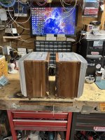
The rolled edge of the tray is supposed to face downwards, there's only one way it can be correct.
Yours is upside down
I think 49V is what you're supposed to have with no load. There's a link somewhere to the commissioning process.. It's certainly on the LuDEF thread..
.. This is it
https://www.diyaudio.com/community/threads/sissysit-r-3.371272/
Yours is upside down
I think 49V is what you're supposed to have with no load. There's a link somewhere to the commissioning process.. It's certainly on the LuDEF thread..
.. This is it
https://www.diyaudio.com/community/threads/sissysit-r-3.371272/
Last edited:
Multiply secondary ACV times 1.4…example: 18VAC x 1.4= 25.2….less loads, say around 2.5-3V depending , gets you close to final VDC. Enough to get you in ballpark
Thank you both. Dim bulb is an entirely appropriate metaphor for me here....seeing just north of 24VDC referenced to ground.
On the tray orientation, from the LuDef thread:
https://www.diyaudio.com/community/threads/ludef.369990/post-6997306
On the tray orientation, from the LuDef thread:
https://www.diyaudio.com/community/threads/ludef.369990/post-6997306
- mains wires underneath base plate must be double insulated; no need to twist them, but mount heatshrink or Tesa cloth tape
- what Boyz wrote above
- if possible - minimize all internal wire lengths, if you already have best routing placement - example - wires from Cap Bank pcbs to motor runs - keep them short
- same color wire for different things ......... I'm not against using same wire color for everything, most of my builds later years are with plain old black for all, but I'm always dressing end of wire with heatshrink of adequate color; that gives you less care while soldering, and looks neater, and allows anyone down the road to see what's inside without banging a head, you not being present to decipher
- just a hint, maybe easier, maybe not - last thing I'm soldering wires to, are channel pcbs; avoiding just one thing as - poking soldering iron near caps on cap bank is somewhat uncomfortable in this moment ..... while you can imagine how hard is soldering rails to channel pcb, amp standing on appropriate heatsink down on the bench; that for future amps ........ I got my routine tricks exactly as result of making wrong choices along the way

On the tray orientation, from the LuDef thread:
tray is good, lip up
mount 4 studs in front plate instead of messing with bolts in the end; much easier to fiddle with nuts for lower two, than to curse while poking with meter long screwdriver
as I wrote in last sentence above - been there, done that

All elements incorporated per advice provided by each of you. PS test #2 ~ 23VDC. Tesa insulation done, Anteks stood up, flipped over, HV twisted/shortened, ready to fire.


Standing the Traffos up is not good advice. The radiated field is much more likely to get into the front end of the amp. This is why almost no OEMs do this.
There's a null in the magnetic field where the wires go in and out (and again on the opposite side), lay them flat and point that part towards the most sensitive part of the amp circuit.
You need to develop a lot more OCD - turn that tray over.
The bottom plate still won't fit, as you haven't used the countersunk bolts that were supplied. Carefully study the picture that was included, it's all there
Standing the Traffos up is not good advice.
tried, it works
One of my quietest set of monoblocks has standing trafos … not shielded either … I did spend some effort with headphones on the outputs tuning stuff.. no rules for me! Whatever works…
Not sure why you're hung up on this. It works just fine in both configurations. There are pros and cons of each to be sure. The countersunk bolts insert from the bottom, so I'm not sure how you know that they're not present... I use them in all my builds where I've flipped the plate and builds where the plate is placed per the manufacturer's intent. Perhaps I missed a photo or other insight. Either way... not disagreeing with you, but I'm curious why you're seemingly passionate about it.You need to develop a lot more OCD - turn that tray over.
The bottom plate still won't fit, as you haven't used the countersunk bolts that were supplied. Carefully study the picture that was included, it's all there
This has been discussed a lot with citations of work showing typical radiation patterns from toroids. It's a tad off topic, and I can take it elsewhere. I actually appreciate when folks challenge 'commonly accepted' practices in the forum. I've mounted some of my toroids vertically for space savings, but also was under the (potentially incorrect) assumption that it was 'better' for radiated fields.... not just because of distance/proximity to sensitive parts of the circuit, but because of directionality.The radiated field is much more likely to get into the front end of the amp.
Based on your comments (and my utter lack of knowledge) I did some brief searches. I know Wikipedia isn't the best of authoritative sources... but minus all the math that I can't and won't try to comprehend... it seems that the "A" field (from link) seems to radiate out of what we'd typically call the top and bottom of the toroid, while the "B" fields effectively cancel. I tend to agree with your statements that for a typical configuration (and if distance is taken out of the equation) that mounting flat would be 'better'.
Again... that's after two readings and with VERY little or no true understanding of the topic at hand. I may have it all backwards. How much it actually matters in a build, I don't know, but tl;dr - I appreciate that you called it out and spurred me to read a bit more. I want to get one of those 'sniffers' or build one...
Infinitely curious ... but consistently a dodo.

https://en.wikipedia.org/wiki/Toroidal_inductors_and_transformers
Standing the Traffos up is not good advice. The radiated field is much more likely to get into the front end of the amp. This is why almost no OEMs do this.
There's a null in the magnetic field where the wires go in and out (and again on the opposite side), lay them flat and point that part towards the most sensitive part of the amp circuit.
Standing has also worked for me.
From my own experience, Antek transformers are the opposite - they leak from the wire locations. I point the wire inlet and outlet away from the amp circuit.
@Zen Mod first attempt at powering each channel individually. Passed dim bulb test, no smoke/smells. Both channels behave same way:
Output climbs past 1V, as it steadily approaches 2V I powered off, per the original SissySit startup protocol ("if >1V at startup something is fishy")
Suggestions please as to how to identify fault. What might I check / measure?
Output climbs past 1V, as it steadily approaches 2V I powered off, per the original SissySit startup protocol ("if >1V at startup something is fishy")
Suggestions please as to how to identify fault. What might I check / measure?

@Zen Mod first attempt at powering each channel individually. Passed dim bulb test, no smoke/smells. Both channels behave same way:
Output climbs past 1V, as it steadily approaches 2V I powered off, per the original SissySit startup protocol ("if >1V at startup something is fishy")
Suggestions please as to how to identify fault. What might I check / measure?
send me pics and your ref. schm
zenmodiyaudio at gmail
write details both for Iq (voltage across 0R11 group, and dc offset (polarity is important))
- Home
- Amplifiers
- Pass Labs
- ZM's 2SK2087C musings, phase two - SissySIT (42) as a cradle