actually bifilar and trifilar can also mean that the wires are twisted into a cable and wrapped around the core, making for very close coupling , but not neccesarily connected in parallel. it could be 2 or 3 separate windings, all the same number of turns and closely coupled. one problem with this is that the inter-winding capacitance is higher than using windings separated by distance around the core. the inter-winding capacitance of a bifilar or trifilar winding is more predictable, and can be measured even before the transformer is wound.
Conta said:Instead of the transformer it is possible to apply the autotransformer. Also the hybrid scheme has advantages:
http://audio.ring.lt/hybrid/hibr2.html
Sorry, text in lithuanian.
You can, but in the event of some kind of failure, you feed the full DC voltage to your speaker.
Sheldon
Conta said:It is true, but the probability that will break a winding of a wire 0,8-1mm is very small.
That is true, however it IS possible to crowbar the mosfet if one exceeds the device's limits, which would put the supply voltage across the speaker. This is why the zener diodes between the Gate and the Source are an absolute MUST HAVE.
Reminder, since the transformer primaries interact and generate a phantom negative rail the mosfet has to have a minimum of twice the power supply voltage plus a safety margin as it's minimum Vdss.
So for a 40 volt nominal supply one has to use a 100V minimum rated mosfet, e.g. IRFP150.
Also look at the mosfet's gain i.e. gfs Forward Transconductance, which for an IRFP150 is typically 14 Siemens (but the IRF150 is only 9).
Note however that this is usually at some high test current, the values of which changes from part to part. This makes it difficult to get absolute comparisons between different mosfet families, see table.
The 2SK1058 has a Forward Transconductance of only 1, but this is at ID = 3 A, VDS = 10 V.
Forward transconductance figures as it will amongst other things affect the output impedance of the amplifier.
I typically bias my mosfets at about 750 mA per device for push-pull circuits as this is usually a good trade-off between dissipation and distortion.
Best wishes,
Susan.
Datasheet comparison of various mosfets:
Device.... Vdss Min Typ Max Forward transconductance @ V,I
========== ==== === === === ==============================
2SK1058... 160V 0.7 1.0 1.4 S VDS = 10V, ID = 3A
EXC20N16.. 160V 1.4 --- 4._ S VDS = 10V, ID = 3A
EXC20N20.. 200V 1.4 --- 4._ S VDS = 10V, ID = 3A
FQA34N20.. 200V --- _26 --- S VDS = 40V, ID = 17A
IRF150.... 100V 9.0 --— --— S VDS > 15V, ID = 24A
IRFP140... 100V _11 ––– ––– S VDS = 50V, ID = 16A
IRFP150... 100V _14 ––– ––– S VDS = 25V, ID = 22A
IRFP250... 200V _17 ––– ––– S VDS = 50V, ID = 18A
IRFP260... 200V _27 ––– ––– S VDS = 50V, ID = 28A
IRFP264... 250V _20 ––– ––– S VDS = 50V, ID = 23A
STW34NB20. 200V __8 _17 --- S VDS > ID(on) x RDS(on)max ID = 17 A
So clear as mud then 🙂
So clear as mud then 🙂
Thank you Susan for your comment. Some time ago I tested this circuit, SE follower (from russian audioforum) with autotransformer output:
http://audio.ring.lt/hybrid/sef.gif
So I'll say it sounds wonderful, clear and dynamic. I tested it with IRF family transistors ant 2SK family too. In my opinion, with 2SK1058 / 2SK1530 amplifier sounds better. IRF transistors is developed for swiching operations commonly, and 2SK... for audio amplifiers. On that score sounds differently.
Morello said:
Maybe you find it nice-sounding due to excessive distortion
😉
Valve amps of this type give out second harmonic distortion whoich sounds great. This is why so many guitarists go for a valve amp or at least an amp with a valve front end.
help with low frequency distorsion with toroid version
I finally assembled a toroid version of Susan Parker’s amplifier to listen how this topology sounds. Since I am very inexperienced with electronics, I followed precisely the directions that Susan Parker was kind enough to share along this thread and on her web sites. Matched STW34NB20 power Mosfets (10mV range), an L200CV bias voltage generator plus temperature tracking Mosfet as described (without thermal switch for now though), a 2x115, 2x24V 30VA input toroid and a, 2x115, 2 x 35V 300 VA output inductor both from Nuvotem. I first installed a 100K multiturns pot as R-term. But changing the values did not make much differences soundwise. So I replaced it by the suggested 10K resistor since I do not know how to tune this precisely.
Electrical features of the amp are : PSU 32V, Amp idle current set to 1A, Mosfet Source to Gate voltage 4.75V, Source to ground (minus star point) voltages through primary windings of the inductor are 124mV on one side, 118mV on the other, and I measure 8mV DC across the speaker terminals.
As line stage, I purchased a Behringer HA4700 headphone-amplifier which can drive loads down to 8 ohms and displays 4 amplifier units. In my hands, its connection to the input toroid as described in post# 362 and depicted by dx.master (http://dx.master.akadns.de/projekte/) resulted in signal cancellation . The problem was solved when the starts of the two primary windings of the input transformer were fed by an identical signal (the right and left signals of two of the HA4700 amps to the start of one primary winding and the remaining left and right signals to the start of the other primary) and grounds to the output of both primaries.
I have been listening to this amp powering a field-coil full-range speaker mounted in open baffle for nine monthes now. The switched-on resting amp is completely quiet and the music coming out of this silence is very good provided it does not contain low basses which are noticeably distorded. With such music, intermodulation and phase distorsions seem very low. In choirs for example, i can easily follow the ‘she’ or ‘he’ making a little bit too much and it is the first time that I can listen to gipsy brass fanfares without frowning, taking pleasure hearing this or that particular instrument intertwining with the band. This also applies to the lines played by group of instruments in classical orchestras which can be followed distinctly. This makes that the tonal quality of instruments is very well transduced. Rendition of piano recordings is the best I ever heard. I have always been somehow disappointed by the dynamics of recorded music in hi-fi systems with respect to life music. I don’t know if using an active linestage participates but here the gap has narrowed. The transition from blackness or low levels to high levels is swift, without compression or edginess. It comes out that interpretation of the Beethoven sonatas by mighty pianists e.g. Richter or Guilels is a real treat.
It is a pity that all these qualities are ruined by significant distorsions in the low end register (contrabasses for example) which make the toroid version of this amp useless to drive fullrange speakers at least. Of course I made all the checks before deciding that the amp was responsible for these distorsions. I bet they are not found with the amp equipped with dedicated input and output transformers such as those sold by Sowther. So because of the high final price tag of this project, I am wondering about the best choice to improve the low requency response of the amp i.e. to buy dedicated input or output transformers ?
Hi Lissitzky,
Although I can't offer much help to you, I'm very interested in your report & it's resolution.
I'm in the process of building one of these amps at the moment & have the power PS & toroid output PS for one channel but for input trafo only have a small audio trafo from here: http://www.oep.co.uk/600ohmCT15ohmCTTransformerA262A1E-pageprodDet-ID51.aspx
I suspect this trafo will suffer in the bass area but I'm surprised the 2x115, 2x24V 30VA input toroid has these issues! Would it have anythingto do with the bias balance between Mosfets - the RTerm?
I'm sure somebody with experience (there are many here), if not Susan herself, will answer you!
Re: help with low frequency distorsion with toroid version
I have just completed a MOSFET amp with 6 IRFP240/9240's on the output. I found 7 volts bias was needed to get rid of crossover distortion which was very severe without any bias.
The bias current wasnt set to a particular current but just enough to get rid of crossover distortion.
Please dont just set your bias to the same as mine as it could be enough to blow your output stage.
Amp idle current set to 1A, Mosfet Source to Gate voltage 4.75V,
[/B]
I have just completed a MOSFET amp with 6 IRFP240/9240's on the output. I found 7 volts bias was needed to get rid of crossover distortion which was very severe without any bias.
The bias current wasnt set to a particular current but just enough to get rid of crossover distortion.
Please dont just set your bias to the same as mine as it could be enough to blow your output stage.
BTW, I'm looking at some input trafo's which might be interesting & certainly seem cheaper than Sowters versions - $350 a pair (for mu-metal laminations) + shipping Here: http://www.intactaudio.com/forum/viewtopic.php?p=3039#3039
Re: toroid amp picture
Hi,
Thank you for your postings and informative feedback.
Ah, thanks for that. Make matters a lot clearer.
I think the Bass problem is from the use of the toroid transformer as a center tapped inductor.
While this works, it is not ideal as there is no impedance transformation which one gets with a proper transformer. I think that there may also be some thermal cycle distortion mechanics also, but that is something I am trying to set up to look at (I need a fast response pyro IR detector which are not cheep).
The use of a mains toroid as a full transformer with the mains primaries connected to the mosfet again isn't ideal as the windings don't couple well at higher frequencies and they are inherently unbalanced.
I do understand the issues about the cost of Sowter's output transformers for my amps, so I have been working on a toroid based design.
The simplest to make is using a 300 to 500 VA core recovered from a regular mains transformer and then tri-filar or quad-filar wind about 200 turns of 1.00 mm magnet wire.
Quad is preferred since I like to have an effective heavier gauge of the pair for the output, but does make the winding a little harder as there are then four wires, each with a mind of it's own, that one is trying to persuade to go neatly around the core.
One can make up a winding spindle from a length of aluminium tube, something about 18" long seems a good compromise between wire length and manageability.
I shall be putting some updates onto my website in the next week or two. Regret I don't have much time at the moment.
Best wishes,
Susan.
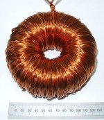
Attached pic is of my first hand wound torroid, with quad-filar 1.00 mm wire.
Hi,
Thank you for your postings and informative feedback.
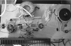
lissitzky said:A picture of the amp build on a piece of wood.
Ah, thanks for that. Make matters a lot clearer.
I think the Bass problem is from the use of the toroid transformer as a center tapped inductor.
While this works, it is not ideal as there is no impedance transformation which one gets with a proper transformer. I think that there may also be some thermal cycle distortion mechanics also, but that is something I am trying to set up to look at (I need a fast response pyro IR detector which are not cheep).
The use of a mains toroid as a full transformer with the mains primaries connected to the mosfet again isn't ideal as the windings don't couple well at higher frequencies and they are inherently unbalanced.
I do understand the issues about the cost of Sowter's output transformers for my amps, so I have been working on a toroid based design.
The simplest to make is using a 300 to 500 VA core recovered from a regular mains transformer and then tri-filar or quad-filar wind about 200 turns of 1.00 mm magnet wire.
Quad is preferred since I like to have an effective heavier gauge of the pair for the output, but does make the winding a little harder as there are then four wires, each with a mind of it's own, that one is trying to persuade to go neatly around the core.
One can make up a winding spindle from a length of aluminium tube, something about 18" long seems a good compromise between wire length and manageability.
I shall be putting some updates onto my website in the next week or two. Regret I don't have much time at the moment.
Best wishes,
Susan.
Attached pic is of my first hand wound torroid, with quad-filar 1.00 mm wire.
Attachments
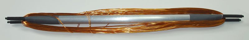
Toroid winding spindle
Here is a pic of my new improved toroid winding spindle which I made up from a length of aluminum tube. It is 18" long, and the ears add about 2" both ends.
The first toroid was wound with a smaller spindle about 12" long that I made from a length of scrap 1/8" thick Tufnol I had to hand, but the "ears" were not strong enough and one broke off part way through winding!
BW,
Susan.
Attachments

Thanks Conta,
Susan is showing us how to wind our own toroid output transformers for the Zeus which is a great service to all those wanting to build one of these amplifiers but put off by the cost of 4 trafos (2 input + 2 output) from Sowter.
Thank you Susan - looking forward to your extra details on your site!
Susan is showing us how to wind our own toroid output transformers for the Zeus which is a great service to all those wanting to build one of these amplifiers but put off by the cost of 4 trafos (2 input + 2 output) from Sowter.
Thank you Susan - looking forward to your extra details on your site!
Re: Re: toroid amp picture
Alternatively, alphacore sells donut transformer cores in small quantity (as in 1 or 2 pcs). Price is good too. See
o-core
http://www.alphacore.com/ocore.htm
c-core
http://www.alphacoredirect.com/index.html?lang=en-us&target=d1.html&lmd=39452.612164
The simplest to make is using a 300 to 500 VA core recovered from a regular mains transformer
Alternatively, alphacore sells donut transformer cores in small quantity (as in 1 or 2 pcs). Price is good too. See
o-core
http://www.alphacore.com/ocore.htm
c-core
http://www.alphacoredirect.com/index.html?lang=en-us&target=d1.html&lmd=39452.612164
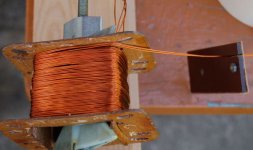
Winding in process:
Thanks for the pic Conta.
Hopefully these images show that it is quite possible to make ones own output transformers by hand.
They do take time to make, and require a bit of setup and preparation too. However the main ingredient (apart from the hardware and lots of wire) is patience.
BW,
Susan.
Thanks for the pic Conta.
Hopefully these images show that it is quite possible to make ones own output transformers by hand.
They do take time to make, and require a bit of setup and preparation too. However the main ingredient (apart from the hardware and lots of wire) is patience.
BW,
Susan.
Re: Re: Re: toroid amp picture
Hi,
Unfortunately for those of us outside the continental USA the shipping charges rapidly become as much if not more than the cores themselves 🙁
For those in the USA then this would seem to be a good starting point.
BW,
Susan.
Hi,
agent.5 said:Alternatively, alphacore sells donut transformer cores in small quantity (as in 1 or 2 pcs). Price is good too. See
o-core
http://www.alphacore.com/ocore.htm
c-core
http://www.alphacoredirect.com/index.html?lang=en-us&target=d1.html&lmd=39452.612164
Unfortunately for those of us outside the continental USA the shipping charges rapidly become as much if not more than the cores themselves 🙁
For those in the USA then this would seem to be a good starting point.
BW,
Susan.
- Home
- Amplifiers
- Solid State
- Zero Feedback Impedance Amplifiers