That distortion
Oooops... Errare humanum est. 🙄
I looked at the transformer distortion test:
http://www.susan-parker.co.uk/zeus-test-2sk1529-fft-1khz.htm
My bad. I looked at wrong numbers.
Harmonic distortion is greater in small signal level than moderate signal level. That is typical for class AB and class B push-pull amplifiers, and there it is crossover distortion.
So, those numbers reminded me of crossover distortion, although it really is transformer distortion.
Anyway, the distortion of the transformer is so small that I don't care.
mikelm said:Hi,
Both the devices are always switched on - so how do we get crossover distortion ?
mike
Oooops... Errare humanum est. 🙄
I looked at the transformer distortion test:
http://www.susan-parker.co.uk/zeus-test-2sk1529-fft-1khz.htm
My bad. I looked at wrong numbers.
Harmonic distortion is greater in small signal level than moderate signal level. That is typical for class AB and class B push-pull amplifiers, and there it is crossover distortion.
So, those numbers reminded me of crossover distortion, although it really is transformer distortion.
Anyway, the distortion of the transformer is so small that I don't care.
Line Drive Amplifiers
About the Tube Line Drive Amplifiers:

http://www.susan-parker.co.uk/zeus-6c33c-line-driver-1.htm
Alan Kimmel told that a pentode is more suitable for a cathode follower compared to a triode.
It seems that (on mu-amplifier figures 3 and 4) the gate-cathode capacitor Cgc is required to move grid 2 potential synchronously with the cathode. That is bad because part of the signal goes through a capacitor, and we already know that part of the beauty of the Zeus amplifier depends on the principle: No capacitors on the signal path. The cathode-grid-connection is also one kind of a feedback, although it is positive feedback. But if the signal for the grid 2 was taken from the input transformer by an extra secondary coil, instead from the cathode output, then it would be more like a feedforward connection, not feedback.
Yes I know these are tube devices, not solid state.
About the Tube Line Drive Amplifiers:
http://www.susan-parker.co.uk/zeus-6c33c-line-driver-1.htm
Alan Kimmel told that a pentode is more suitable for a cathode follower compared to a triode.
http://www7.taosnet.com/f10/mustage.htmlA pentode CF has several advantages over triode CFs, including lower input capacitance, larger voltage swing, lower output impedance. and lower attenuation.
It seems that (on mu-amplifier figures 3 and 4) the gate-cathode capacitor Cgc is required to move grid 2 potential synchronously with the cathode. That is bad because part of the signal goes through a capacitor, and we already know that part of the beauty of the Zeus amplifier depends on the principle: No capacitors on the signal path. The cathode-grid-connection is also one kind of a feedback, although it is positive feedback. But if the signal for the grid 2 was taken from the input transformer by an extra secondary coil, instead from the cathode output, then it would be more like a feedforward connection, not feedback.
Yes I know these are tube devices, not solid state.
wattage on 12v
Hi Sheldon,
How many watts are you getting with 12v ? This might be a good alternative to tubes for car use.
Hi Sheldon,
How many watts are you getting with 12v ? This might be a good alternative to tubes for car use.
Re: wattage on 12v
I haven't measured, but calculation should give a reasonable estimate. With a 12V supply it should be able to swing about +/-9V. Therefore, the output will be 18/1.4/2, or 6.4Vrms. Since power output is Vrms, squared, divided by load impedance (6.4*6.4/8), I figure about 5 watts into an 8ohm load.
Looking at current requirements; 6.4Vrms over 8 ohms will generate a current of 0,8A. Since the transformer steps the current up by a factor of two, this requires a bias current of at least 0.4A to operate in class A up to the output limit (though I don't think the devices themselves actually cut off completely, even at lower current).
Sheldon
vizion said:Hi Sheldon, How many watts are you getting with 12v ? This might be a good alternative to tubes for car use.
I haven't measured, but calculation should give a reasonable estimate. With a 12V supply it should be able to swing about +/-9V. Therefore, the output will be 18/1.4/2, or 6.4Vrms. Since power output is Vrms, squared, divided by load impedance (6.4*6.4/8), I figure about 5 watts into an 8ohm load.
Looking at current requirements; 6.4Vrms over 8 ohms will generate a current of 0,8A. Since the transformer steps the current up by a factor of two, this requires a bias current of at least 0.4A to operate in class A up to the output limit (though I don't think the devices themselves actually cut off completely, even at lower current).
Sheldon
Pentode Zeus
Because this is Solid State discussion, I posted a new thread about a pentode version to the Tubes forum. Read it there:
http://www.diyaudio.com/forums/showthread.php?threadid=105804
Because this is Solid State discussion, I posted a new thread about a pentode version to the Tubes forum. Read it there:
http://www.diyaudio.com/forums/showthread.php?threadid=105804
I got an idea
If I had a very low impedance loudspeaker, I would not need voltage amplification.
Just an attenuator and a voltage follower current amplifier stage.
It would look something like this:
No audio transformers here.
The 0.2 ohm full range speaker as in the drawing is a missing component.
If I had a very low impedance loudspeaker, I would not need voltage amplification.
Just an attenuator and a voltage follower current amplifier stage.
It would look something like this:
An externally hosted image should be here but it was not working when we last tested it.
No audio transformers here.
The 0.2 ohm full range speaker as in the drawing is a missing component.
More practical version
Since I don't know any 0.2 ohm full range speakers, an input transformer may be an acceptable alternative.
Since I don't know any 0.2 ohm full range speakers, an input transformer may be an acceptable alternative.
An externally hosted image should be here but it was not working when we last tested it.
better measurements for the jfet version
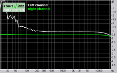
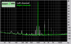
Those measurements on the previous page were faulty, due to a toasted soundcard. Here are some better ones. First, frequency response. I should note that I'm using the amp above 300 Hz, and have gapped the OPT's, so I purposely focused on response above that in the design. The green trace is the soundcard control:
Those measurements on the previous page were faulty, due to a toasted soundcard. Here are some better ones. First, frequency response. I should note that I'm using the amp above 300 Hz, and have gapped the OPT's, so I purposely focused on response above that in the design. The green trace is the soundcard control:
Attachments
ribbon driver
Dear Susan and all,
I’ve been looking for a solution to directly drive the .05 ohm ribbons of my Raal tweeters for a while. Maybe this amp is it?
I would really appreciate your help though as I find it easy to make mistakes with transformer turns ratios etc.
My idea is to wind a trifilar OPT with 60 turns and wire all the secondaries in parallel/or pairs in parallel. Would this reflect the correct impedance to the mosfets? I’m looking for maximum 8 watts output, would a 12v lead acid battery get me there?
I think I have enough drive from my DAC OPT transformer (Lundahl 1674 driven by a 6n6p push-pull). I have a small stack of nickel laminations that came from a previous tweeter transformer. I will be using 1st order of 4500hz.
I’d be very interested in any comments
Many thanks, james
Re: ribbon driver
With a single trifilar bobbin, without tapping the windings, the only option is a 2:1 OPT. If you assume a net of 10V maximum at the transformer, that gives a swing of 20V across the primary and 10V across the secondary. Divide that by 1.4 to get 7.2V. So the maximum is about (7.2x7.2)/8 = 6.5W. With the same set up, I get about 6W before clipping.
If you wind quad filar and connect the secondary in series for a 1:1 transformer you will get twice the voltage swing and 4 times the power. Or if you just want to double the power, you can increase the supply voltage by a factor of 1.4.
Sheldon
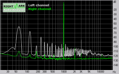
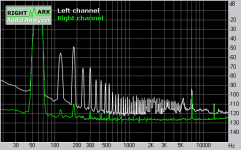
By the way, even those recent measurements were faulty. New sound card, but noisy set up. Cleaned that up. I also added a buffer in line with the sound card. The input transformer likes a lower impedance drive than my sound card allows.
This begs the question: Why battery power? This amp has very good PSRR.
This begs the question: Why battery power? This amp has very good PSRR.
Attachments
thanks for explaining the power output vs. PSU voltage. I get it now.
As for the transformer... i didn't write clearly what I meant.
I was imagining 30 secondaries in parallel - making a 60:1 transformer. This should reflect 180 ohms from my 0.05 ribbon shouldn't it? I would be quite tricky to get the 30 turns connected in parallel. but not impossible. or maybe I'm up the wrong tree here...?
as for the battery... i have one already installed in each speaker...
james
[email]JAMES@BOYD.ORG[/email] said:As for the transformer... i didn't write clearly what I meant.
I was imagining 30 secondaries in parallel - making a 60:1 transformer. This should reflect 180 ohms from my 0.05 ribbon shouldn't it? I would be quite tricky to get the 30 turns connected in parallel. but not impossible. or maybe I'm up the wrong tree here...?
Yes, wrong tree. First, it doesn't matter how many secondaries you connect in parallel as far as impedance conversion goes - 1 wire or 100 wires. All you do is lower the DC resistance. It's the same as using bigger wire. The only thing that matters is how many times the winding (single or parallel) goes around the bobbin, compared to how many times the primary goes around. Turns (number of trips around) are not the same as windings (number of wires).
I didn't realize you were trying to drive the ribbon directly. If you really want to drive 0.05 ohms directly, you need 160 times the current that would be required to drive 8 Ohms to the same power, (and 1/160th of the voltage). That means you need a turns ratio 160 times greater than to drive 8 Ohms. Say you want the same output as a 2:1 transformer (160 turns trifilar - two windings for the center tapped primary, one for the secondary) If your primary is 160 turns, you need 1 turn for the secondary. I'm a rank amateur when it comes to winding transformers, but I guess that the single turn could be however many parallel windings it takes to span the bobbin. Of course, you could make two secondary turns for a 80:1 transformer. You'd have to get some advise on how to wind to get good coupling at your frequencies. I have no idea if this kind of transformer is feasible.
All that said, what do you have against the transformer that is supplied with the Raal? You better know your stuff if you expect to make something better.
Sheldon
strange reply.
You say I'm up the wrong tree, then you go on to calculate more or less what what I've proposed. i.e. 30 secondary windings in parallel = 1 winding against 60 primary. And yes, DC resistance IS important when driving 0.05 ohms.
thanks though
You say I'm up the wrong tree, then you go on to calculate more or less what what I've proposed. i.e. 30 secondary windings in parallel = 1 winding against 60 primary. And yes, DC resistance IS important when driving 0.05 ohms.
thanks though
Re: ribbon driver
Ah OK, I didn't understand what you meant by trifilar OPT with 60 turns. The conventional meaning for that is three wires wound in parallel, 60 turns. Your follow up post wasn't clear to me either, but I understand now. Just to make sure, you mean 60 turns, bifilar for the primary, and 1 turn 30 filar for the secondary, all secondaries connected in parallel.
For clarity's sake let me repeat, it's not "1 winding against 60 primary", it's 1 secondary turn against primary 60 turns. A winding can be 1 turn or 1000 or 10,000 turns. One turn is one turn. I'm often confused as a matter of constitution, don't make it worse.
Carry on.
Sheldon
edit: might consider making that secondary from copper foil instead of wire
[email]JAMES@BOYD.ORG[/email] said:My idea is to wind a trifilar OPT with 60 turns and wire all the secondaries in parallel/or pairs in parallel.
[email]JAMES@BOYD.ORG[/email] said:strange reply.
You say I'm up the wrong tree, then you go on to calculate more or less what what I've proposed. i.e. 30 secondary windings in parallel = 1 winding against 60 primary. And yes, DC resistance IS important when driving 0.05 ohms.
Ah OK, I didn't understand what you meant by trifilar OPT with 60 turns. The conventional meaning for that is three wires wound in parallel, 60 turns. Your follow up post wasn't clear to me either, but I understand now. Just to make sure, you mean 60 turns, bifilar for the primary, and 1 turn 30 filar for the secondary, all secondaries connected in parallel.
For clarity's sake let me repeat, it's not "1 winding against 60 primary", it's 1 secondary turn against primary 60 turns. A winding can be 1 turn or 1000 or 10,000 turns. One turn is one turn. I'm often confused as a matter of constitution, don't make it worse.
Carry on.
Sheldon
edit: might consider making that secondary from copper foil instead of wire
Instead of the transformer it is possible to apply the autotransformer. Also the hybrid scheme has advantages:
http://audio.ring.lt/hybrid/hibr2.html
Sorry, text in lithuanian.
http://audio.ring.lt/hybrid/hibr2.html
Sorry, text in lithuanian.
- Home
- Amplifiers
- Solid State
- Zero Feedback Impedance Amplifiers