Thank you all, thank you Susan for the support,
Thank you for pointing that out. I was thinking the other way around and was about to order input transformers from Sowter which I will do anyway at some point.
I will examine the output transformer issue and keep you informed.
Thank you again
I think the Bass problem is from the use of the toroid transformer as a center tapped inductor
Thank you for pointing that out. I was thinking the other way around and was about to order input transformers from Sowter which I will do anyway at some point.
I received a 30 ohm 8" field-coil fullrange speaker made for me last week but have not had time to hook up the Zeus amp to it. The higher impedance might help.While this works, it is not ideal as there is no impedance transformation which one gets with a proper transformer.
Have not had problems with high frequencies transduction. So if its even better huh!a full transformer with the mains primaries connected to the mosfet again isn't ideal as the windings don't couple well at higher frequencies and they are inherently unbalanced
I will examine the output transformer issue and keep you informed.
Thank you again
Hi,
Okay 🙂
If you still want to do something about the input side, you could replace the straight R termination with a series RC termination.
The main point of the termination is to manage the inductive kick up one usually gets at the HF end of the transformer bandwidth.
There are two ways of reducing this effect.
1: Increase the driving impedance (by adding series resistance). At some point the transformer will show a flat response.
However the distortion will rise proportionately as the key to getting low distortion out of transformers is to drive with lower rather than higher impedances.
2: Use a termination load.
With a Sowter 1+1:10+10 input transformer, with the primaries in series, a good driving impedance seems to be about 50 ohms. Lower than c. 50 and the HF inductive kick up is very strong, above c.50 and the bandwidth suffers.
In your situation using the toroid input transformer, starting with say 10K and 1nF you would need to do a signal sweep and look for kick up or early roll off, then adjust the values to make it flat.
The use of the RC termination will then remove the loading lower down, so the bass region will only have to contend with the impedance fall off of the inductor as it approaches DC.
For the Sowter using a series RC termination I have been using 120K plus 10nF. Remembering this is dependent on driving impedance so there is no "one value fits all" situation.
That should make a big difference as 30 ohms is about ideal for use direct across the swinging inductor arms (32 ohms is equal to using 8 ohms in 2:1 mode).
With the swinging inductor arrangement you are using the HF performance should be very good and will be limited by the input signal rather than the mosfets (which should be good for 1MHz plus).
Please. Look forward to your report, particularly with regard to the bass issue.
Best wishes,
Susan.
Originally posted by lissitzky
... snip ...
Thank you for pointing that out. I was thinking the other way around and was about to order input transformers from Sowter which I will do anyway at some point.
Okay 🙂
If you still want to do something about the input side, you could replace the straight R termination with a series RC termination.
The main point of the termination is to manage the inductive kick up one usually gets at the HF end of the transformer bandwidth.
There are two ways of reducing this effect.
1: Increase the driving impedance (by adding series resistance). At some point the transformer will show a flat response.
However the distortion will rise proportionately as the key to getting low distortion out of transformers is to drive with lower rather than higher impedances.
2: Use a termination load.
With a Sowter 1+1:10+10 input transformer, with the primaries in series, a good driving impedance seems to be about 50 ohms. Lower than c. 50 and the HF inductive kick up is very strong, above c.50 and the bandwidth suffers.
In your situation using the toroid input transformer, starting with say 10K and 1nF you would need to do a signal sweep and look for kick up or early roll off, then adjust the values to make it flat.
The use of the RC termination will then remove the loading lower down, so the bass region will only have to contend with the impedance fall off of the inductor as it approaches DC.
For the Sowter using a series RC termination I have been using 120K plus 10nF. Remembering this is dependent on driving impedance so there is no "one value fits all" situation.
I received a 30 ohm 8" field-coil fullrange speaker made for me last week but have not had time to hook up the Zeus amp to it. The higher impedance might help.
That should make a big difference as 30 ohms is about ideal for use direct across the swinging inductor arms (32 ohms is equal to using 8 ohms in 2:1 mode).
Have not had problems with high frequencies transduction. So if its even better huh!
With the swinging inductor arrangement you are using the HF performance should be very good and will be limited by the input signal rather than the mosfets (which should be good for 1MHz plus).
I will examine the output transformer issue and keep you informed.
Please. Look forward to your report, particularly with regard to the bass issue.
Best wishes,
Susan.
Dear Susan, Thank you for these very informative comments.
I will try the RC damping termination as soon as possible.
I did some listening last night with the 32 ohm speaker and bass distorsions seem significantly lower indeed.
I will report of my progresses with your amp.
Thank you.
I will try the RC damping termination as soon as possible.
I would have aimed at much lower than these figures due to Nemestra posts # 1116 and 1117 showing the low impedance of the amp at low frequencies and a decrease of distorsions at these frequencies with low impedance sources. Apparently nothing comes as a free lunch.With a Sowter 1+1:10+10 input transformer, with the primaries in series, a good driving impedance seems to be about 50 ohms. Lower than c. 50 and the HF inductive kick up is very strong, above c.50 and the bandwidth suffers.
I did some listening last night with the 32 ohm speaker and bass distorsions seem significantly lower indeed.
I will report of my progresses with your amp.
Thank you.
As per Nemestra's posts mentioned above - I'm going the two stage route and combining a unique & unusual BDT preamp with the unique & unusual Zeus power amp.
The BDT preamp is a Beam Deflection TV Tube which effectively has oodles of gain if needed & great driving capabilities in balanced or single ended mode with upto 100V swing. Thread here: http://www.diyaudio.com/forums/showthread.php?s=&threadid=123402
I'll be trying a toroidal interstage transformer (instead of the Zeus input trafo) first while I'm waiting on my Dave Slagle custom trafos from the US (only about the same price as the Sowter Zeus input trafos).
The toroids I'll be trying are the model 70005 from Nuvotem - a 1.6VA 115-0-115:22-0-22 connected with primaries towards BDT & secondaries to Zeus giving about 1:4 step-down, I think? How does all this stack up so far - I'm just using other peoples advice to put this together, I'm afraid I don't know much if anything about impedance matching so I hope this all looks right?
This will eventually be replaced by a 1:1 custom made trafo!
Hope to be able to report back next week on the sound!
Single ended Zeus
Is there anyone who has built the single ended version of the Zeus amp?
To me it looks like a prime candidate for high sensitivity spherical horns.
Is there anyone who has built the single ended version of the Zeus amp?
To me it looks like a prime candidate for high sensitivity spherical horns.
You'd have to work out a scheme to buck the quiescent current in the OPT for a single ended amp. It would have to track the current well. Doable, but easier to just go with PP.
Sheldon
Sheldon
Single ended Zeus Post #1265
Is there anyone who has built the single ended version of the Zeus amp?
To me it looks like a prime candidate for high sensitivity spherical horns.
Hybrid-SE follower some time ago was discussed in russian DIY forum:
http://audioportal.su/forums/showpost.php?p=239385&postcount=170
Hi Stee,
The Zeus is already balanced - can you say what are the advantages to your circuit? Have you built it? Can you explain your chematic?
The Zeus is already balanced - can you say what are the advantages to your circuit? Have you built it? Can you explain your chematic?
It's a true H-bridge complementary follower, while the Zeus is a U-bridge (the top half basically, using only like devices). Also, it doesn't make use of the "rail generation" like the Zeus (because it's not needed), and there is no bias current through the xformer. In fact the xformer is only used as a step-up, you could as well attach your speaker directly.
BTW, one could do this direct attachment with the Zeus also, replacing the output xformer with an appropriate center-tapped choke. Anybody having thought of this or something similar (except those two australian guys and a third one in SoCal, you know who you are ;-), or actually tried it?
- Klaus
BTW, one could do this direct attachment with the Zeus also, replacing the output xformer with an appropriate center-tapped choke. Anybody having thought of this or something similar (except those two australian guys and a third one in SoCal, you know who you are ;-), or actually tried it?
- Klaus
KSTR said:BTW, one could do this direct attachment with the Zeus also, replacing the output xformer with an appropriate center-tapped choke. Anybody having thought of this or something similar (except those two australian guys and a third one in SoCal, you know who you are ;-), or actually tried it?
- Klaus
You could do it that way, but I don't see an advantage. Coupling of the tri or quad filar transformer should be very good. The disadvantage of the choke is that if one of the output devices loses its magic smoke, the speaker will follow. As the transformer for this application is as easy to wind as a choke (actually easier for the tri-filar tranny, because you have no taps to deal with), might as well have the insurance.
Sheldon
[email]JAMES@BOYD.ORG[/email] said:thanks for explaining the power output vs. PSU voltage. I get it now.
As for the transformer... i didn't write clearly what I meant.
I was imagining 30 secondaries in parallel - making a 60:1 transformer. This should reflect 180 ohms from my 0.05 ribbon shouldn't it? I would be quite tricky to get the 30 turns connected in parallel. but not impossible. or maybe I'm up the wrong tree here...?
as for the battery... i have one already installed in each speaker...
james
James,
Another way to make your Ribbon interface transformer is to use
copper foil or sheet for the secondaries. This is a more efficient fill
factor wise and impedance wise than paralleling many turns of
wire.
I had used this method in the past for very high current power
transformers.
cheers,
Terry
OK, more dumb questions - does this have inherent advantages? I guess not needing a bias is one but are there others of sonic benefit? Does the variable pot allow exact matching of both sides? Where is the input to & where is the output from on the schematic?
I'm in the process of building a Zeus amp & am interested in variations
I'm in the process of building a Zeus amp & am interested in variations
The inherent protection is a good point, I completely agree. On the coupling issue, I'd say that the choke also need to be bifilar wound when high quality is wanted. Advantage, besides an extended freq range, is the more effcient use of copper. For protection I'd always use the usual circuits for DC and SOA/thermal issues, plus a DC servo.Sheldon said:As the transformer for this application is as easy to wind as a choke (actually easier for the tri-filar tranny, because you have no taps to deal with), might as well have the insurance.
EDIT: Wrong conclusions deleted
- Klaus
Zeus FULL-BRIDGE
thanks Kalus
there is another good plus about balanced Zeus:
you can have AB biasing and the sound of A class amplifier
because N and P channel working togheter
I have to drawing it better... (bias resistors are wrong)
😉
KSTR said:It's a true H-bridge complementary follower, while the Zeus is a U-bridge (the top half basically, using only like devices). Also, it doesn't make use of the "rail generation" like the Zeus (because it's not needed), and there is no bias current through the xformer. In fact the xformer is only used as a step-up, you could as well attach your speaker directly.
BTW, one could do this direct attachment with the Zeus also, replacing the output xformer with an appropriate center-tapped choke. Anybody having thought of this or something similar (except those two australian guys and a third one in SoCal, you know who you are ;-), or actually tried it?
- Klaus
thanks Kalus
there is another good plus about balanced Zeus:
you can have AB biasing and the sound of A class amplifier
because N and P channel working togheter
I have to drawing it better... (bias resistors are wrong)
😉
Thanks Stee,
Would you draw it again, please? As I said I'm in the process of building the Zeus and may well give this circuit a go if there are advantages - I have 4 pairs of matched IRFP240 & IRFP9240.
What are the requirements for the output trafo - same as the Zeus?
Would you draw it again, please? As I said I'm in the process of building the Zeus and may well give this circuit a go if there are advantages - I have 4 pairs of matched IRFP240 & IRFP9240.
What are the requirements for the output trafo - same as the Zeus?
yes exactly the same but symmetrical
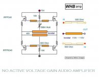
http://www.susan-parker.co.uk/zeus-toroid-amp-1.htm
better have balanced source like Lite DAC
http://cgi.ebay.it/LITE-Hi-End-Mini...Z3280QQcmdZViewItemQQ_trksidZp1742.m153.l1262
but in this case you have to connect cold transformer in reversal polarity
http://www.susan-parker.co.uk/zeus-toroid-amp-1.htm
better have balanced source like Lite DAC
http://cgi.ebay.it/LITE-Hi-End-Mini...Z3280QQcmdZViewItemQQ_trksidZp1742.m153.l1262
but in this case you have to connect cold transformer in reversal polarity
Attachments
Ah, I see that Susan herself has tried the choke loaded variant... unfortunately not much further info available from her side, it seems. An additional option for those who want lowest possible output impedance would be to reference the input xformer windings not to circuit common (bias, that is), but each winding to the opposite end of the load instead (and manage to bias it correctly, of course, preferable in the D2S-region of the used MOSFETs). This would require two times the drive voltage.Stee said:
- Klaus
Hhm, you'd need a pretty decent biasing circuitry with this, since there are no degeneration resistors, this could easily cause thermal runaway/destruction. That's the nice thing about the original design, especially with the choke-loaded variant: There you have the DC resistance of the windings as degeneration resistor, but it's common mode, not in series with the load.Stee said:yes exactly the same but symmetrical
-Klaus
Sheldon said:You'd have to work out a scheme to buck the quiescent current in the OPT for a single ended amp. It would have to track the current well. Doable, but easier to just go with PP.
Sheldon
Thanks Sheldon & Conta !
I have noticed SE version has much lover output impedance than PP (0.8 ohm versus 2.7 ohm).
- Home
- Amplifiers
- Solid State
- Zero Feedback Impedance Amplifiers