fivestring said:Thanks Sheldon & Conta !
I have noticed SE version has much lover output impedance than PP (0.8 ohm versus 2.7 ohm).
That's because the transformer shown is 1:1. If you make it 1:4, I think the output impedance is closer to the 2.7R. BTW, that SE version is designed to drive a 600 Ohm load, so the transformer core doesn't have to do much work. If you want to drive a speaker load, you will have to balance the current in transformer, or have a huuuge core.
Sheldon
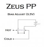
adjusting bias on Zeus Full Bridge
hello
just a double potentiometer for PP biasing
don't need:
1- class A bias - set around 7V gate to gate
2- ground (no dual power supply)
3- special output transformer - it's ok a toroidal PSU with secondary as primary and viceversa (no active VAS)
hello
just a double potentiometer for PP biasing
don't need:
1- class A bias - set around 7V gate to gate
2- ground (no dual power supply)
3- special output transformer - it's ok a toroidal PSU with secondary as primary and viceversa (no active VAS)
Attachments
Re: Zeus FULL-BRIDGE
Hi Stee,
If you are going to use complementary transistors to achieve bidirectional current flow, then why keep the output transformer?
Aside from speaker protection against dc faults.
Brian
Stee said:
thanks Kalus
there is another good plus about balanced Zeus:
you can have AB biasing and the sound of A class amplifier
because N and P channel working togheter
I have to drawing it better... (bias resistors are wrong)
😉
Hi Stee,
If you are going to use complementary transistors to achieve bidirectional current flow, then why keep the output transformer?
Aside from speaker protection against dc faults.
Brian
no active VAS philosophy
ciao Brian
there is one current of designer that don't love VAS
so you need a transformer to have voltage gain
for example:
http://www.royaldevice.com/RUBINA-EVOLUZIONE-eng.htm

really my research is not as integrist
I'm working on the levy of a reduced profit of voltage directly from a FET mirror current
through the use of a pair of capacitors...
ciao Brian
there is one current of designer that don't love VAS
so you need a transformer to have voltage gain
for example:
http://www.royaldevice.com/RUBINA-EVOLUZIONE-eng.htm
really my research is not as integrist
I'm working on the levy of a reduced profit of voltage directly from a FET mirror current
through the use of a pair of capacitors...
ciao Stee,
That website has some sexy looking gear. Just what I expect from an Italian design house. I love the bold use of transformers.
I really like Susan's idea of using transistors in a traditional tube architecture. Very few parts, very simple architecture. The transformer design is a pig, though.
But I initially thought the real advantage from a sound quality point of view was simplicity and using all n-channel transistors. This is why I thought your post involving adding p-channels was incongruous.
I hadn't considered the avoidance of a VAS stage. That's nice. But I'm not convinced an output transformer is required. Can the design simply have a step-up input transformer, then a push-pull buffer, then a direct connection to a speaker?
Brian
Hi,
The problem with an input step-up is that the load capacitance from the MOSFETs gets multiplied with the squared step-up ratio, so you need either a very low-Z driver, or buffers in front of the MOSFETs (I'd prefer the latter, since this seems to be a better working environment for the xformer). Basically I like xformers as "VAS" pretty much, or at least as a floating coupling means... then one can use a simple impedance buffer with a 1:1 xformer and still have arbitrary voltage gain. With DC-coupling the buffer must be low offset/drift (to avoid uncontrolled bias shift issues), and obviously it should have low distortion, too, because these errors get multiplied with the voltage gain.... no free lunch...
- Klaus
ciao
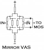
I'm not convinced an output transformer is required too.
Can the design simply have a natural sound in VAS?
My idea is that critical VAS need a mirror for better accuracy
so the input mirror must be VAS in the same time...
see this drawing
imaging 2SK170/2SJ74
then need just little hexfet in current (common surce) like IRF610/IRF9610 + last stage with big bipolar (common emitter)
😱
Attachments
susan's amp
.
.
I think one of the major keys to the great sound of this amp is that it has extremely low noise. Any noise generated by the supply ( of which there will be a lot ) is almost perfectly cancelled the almost perfect symmetry of the windings of the transformer or choke.
So if ur planning to eliminate the transformer / choke then I guess u have to figure out if u can think of an equally good way of keeping the noise down at such sublimely low levels.
Susan's passive VAS will have almost no noise, the cct you showed seems to have a lot of resistors. In my experience resistors, unless they are very expensive types, sound dreadful.
So my guess would be that the resulting amp would not sound as good as susan's - which I have heard - but, of course, I might be completely wrong.
.
.
I think one of the major keys to the great sound of this amp is that it has extremely low noise. Any noise generated by the supply ( of which there will be a lot ) is almost perfectly cancelled the almost perfect symmetry of the windings of the transformer or choke.
So if ur planning to eliminate the transformer / choke then I guess u have to figure out if u can think of an equally good way of keeping the noise down at such sublimely low levels.
Susan's passive VAS will have almost no noise, the cct you showed seems to have a lot of resistors. In my experience resistors, unless they are very expensive types, sound dreadful.
So my guess would be that the resulting amp would not sound as good as susan's - which I have heard - but, of course, I might be completely wrong.
The disadvantage of the choke is that if one of the output devices loses its magic smoke, the speaker will follow.
Hi Sheldon !
Please concider the low DC resistance of the choke. The choke will be in parallel with the loudspeaker and only a small part of any DC will pass through the speaker. So nobody should be scared away from experimenting with chokes. 😉
Thorsten Larsen
thorstenlarsen said:Please concider the low DC resistance of the choke. The choke will be in parallel with the loudspeaker and only a small part of any DC will pass through the speaker. So nobody should be scared away from experimenting with chokes. 😉
Good point. As long as the choke has continuity end to end, most of the current would pass through the choke. Experiment away.
Sheldon
This will be my next amplifier project when I have some $$ again.
Is it possible to wind the output transformer so that you could include a switch to change between 4:1 and 2:1 output?
Cheers,
Alex
Is it possible to wind the output transformer so that you could include a switch to change between 4:1 and 2:1 output?
Cheers,
Alex
Alex from Oz said:This will be my next amplifier project when I have some $$ again.
Is it possible to wind the output transformer so that you could include a switch to change between 4:1 and 2:1 output?
Cheers,
Alex
It's wound that way as is: http://www.susan-parker.co.uk/zeus-sowter-1stage-1-large.gif
For 4:1 the four secondary windings are connected in parallel. For 2:1, you'd wind 2 in parallel, by 2 in series.
To make it easier, label the secondary leads 1-8 from top to bottom. As shown for 4:1 the connections would be 1-3-5-7, and 2-4-6-8. For 2:1 the connections would be 1-3, 2-5, 4-7, and 6-8. To switch from 4:1 to 2:1, you'd break connections 3-5-7, and 2-4-6, and make connections 2-5 and 4-7.
Sheldon
Hi!
I have some questions:
1. How can I calculate the output power of the Zeus amp?
2. Susan sugested to make the OPT with Quad Filar wound and
No insulation between the layers. But what about the Primary leakage inductance and capacitance? Don't we need to use different winding techniques, such as interleaving etc.?
3. What would be the best toroid transformer for a 35W Zeus with 6-8 Ohm speakers?? I can make any voltage variations.
Maybe a 4x24Vac 150VA?
4. Is it possible to use an insulated (PolyP or teflon) solid core copper wire?
Greets:
Tyimo
Tyimo said:How can I calculate the output power of the Zeus amp?
Take your supply voltage and subtract about 5 to account for the bias voltage. That gives you your maximum peak voltage. Multiply that number times 2 for peak to peak voltage across the primary. Divide by 1.4 to get RMS voltage. Divide that number by your transformer ratio, square it, and divide by your load resistance to get power.
Example for 50V power supply, 4:1 transformer and 8 Ohm load: 50-5 = 45Vpeak. 45x2/1.4 = 64vRMS. 64/4 = 16vRMS output. 16x16/8 = 32W output.
Tyimo said:Susan sugested to make the OPT with Quad Filar wound and
No insulation between the layers. But what about the Primary leakage inductance and capacitance? Don't we need to use different winding techniques, such as interleaving etc.?
Leakage inductance will be lowest with quad filar winding, as coupling between primary and secondary is best this way. The number of turns in this transformer is much lower than a typical output transformer, so the interwinding capacitance will also be low enough to avoid capacitive coupling in the audible frequency range.
Tyimo said:What would be the best toroid transformer for a 35W Zeus with 6-8 Ohm speakers?? I can make any voltage variations.
Maybe a 4x24Vac 150VA?
See answer to #1 for DC voltage requirements. Susan recommends a supply transformer rated for 3x the steady state power output of the amp.
Tyimo said:Is it possible to use an insulated (PolyP or teflon) solid core copper wire?
You can use any wire you want, as the voltage insulation requirements are low. For the transformer, the limiting factor will be space taken up by the insulation. I see no advantage to exotic insulation here. Regular magnet wire will be the cheapest, and work as well as any other.
Sheldon
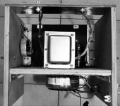
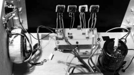
Monoblock Finished
I have now finished to assemble two monoblocks using toroid input transformers for now (2x115, 2x24V 30VA input toroids terminated by 10K in series with 1nF) and dedicated Sowter 9840 output transformers in a 4 :1 configuration. Connection of the primaries of the latter was a bit puzzling since I got very little output and distortion when connections were made as indicated in http://www.audiophonics.com/images/schematics/zeus-sowter-1stage-1-600.gif (???). Problem was solved when primaries of each of the bobins were connected in series (#6 with #7 in the above figure) or as indicated in post # 1166 which is now the definitive arrangement.
The amps now drive the 30R fullrangers fluently : Bye-bye bass distorsions (no postcard please !). They are the amps for the rest of my life ! Program : buy their dedicated input transformers and build the line driver which should be : S&B TX102 (+6dB)> buffer (Jisbos probably) > Lundhal LL1684 (phase splitting) > STP55NE06 mosfets based mini-Zeus (http://www.susan-parker.co.uk/zeus-line-driver-1.htm) > Sowter 9840 1 :2 may be asked to be wound with thinner wires since ref 9846 for T2 has disappeared. Thank you Susan Parker for sharing this excellent invention and for your support.
Attachments
Re: Monoblock Finished
Nice! Yes, that figure always confused me. As drawn, the primaries appear connected in antiphase from one side of the split bobbin to the other. And yes, the amp does require a low impedance source.
Sheldon
lissitzky said:I have now finished to assemble two monoblocks using toroid input transformers for now (2x115, 2x24V 30VA input toroids terminated by 10K in series with 1nF) and dedicated Sowter 9840 output transformers in a 4 :1 configuration. Connection of the primaries of the latter was a bit puzzling since I got very little output and distortion when connections were made as indicated in http://www.audiophonics.com/images/schematics/zeus-sowter-1stage-1-600.gif (???). Problem was solved when primaries of each of the bobins were connected in series (#6 with #7 in the above figure) or as indicated in post # 1166 which is now the definitive arrangement.
The amps now drive the 30R fullrangers fluently : Bye-bye bass distorsions (no postcard please !). They are the amps for the rest of my life ! Program : buy their dedicated input transformers and build the line driver which should be : S&B TX102 (+6dB)> buffer (Jisbos probably) > Lundhal LL1684 (phase splitting) > STP55NE06 mosfets based mini-Zeus (http://www.susan-parker.co.uk/zeus-line-driver-1.htm) > Sowter 9840 1 :2 may be asked to be wound with thinner wires since ref 9846 for T2 has disappeared. Thank you Susan Parker for sharing this excellent invention and for your support.
Nice! Yes, that figure always confused me. As drawn, the primaries appear connected in antiphase from one side of the split bobbin to the other. And yes, the amp does require a low impedance source.
Sheldon
Athough I haven't read the entire thread,I am interested in using one of there amps to drive the 16 ohm compression driver/horn in my active Altec system.
My question is;would anybody be prepared to build this for me(I am an electrocution risk soldering anything but interconnects )?
)?
I live in Australia,and will receive replies given on this thread(via notification).
Many thanks.
My question is;would anybody be prepared to build this for me(I am an electrocution risk soldering anything but interconnects
)?I live in Australia,and will receive replies given on this thread(via notification).
Many thanks.
- Home
- Amplifiers
- Solid State
- Zero Feedback Impedance Amplifiers