What are the best mosfets ?
.
I am just building another Zeus - my first attempt is in the UK and I am now in USA . . . .
I would be glad of any advice about what are the best mosfets to use . . .I seem to remember seeing something about that recently but I cannot find it now.
I plan to have about 32 Volts on the rail and 1.5 amps through each device.
all advice welcome
thanks
mike
Tyimo said:Hi Sheldon!
Thank you very much!!
I understand now!
Only one problem:
with 34V PSU and 2:1 transformer and 8 Ohm speaker
I got 1.29 A on the primary.
On the Zeus page I saw for the 35W version: 34Vdc, 2:1 transformer, and 500-750mA bias.
Greets:
Tyimo
the extra current will give you lower distortion . . . 🙂
in my world extra current is good . . . .
but if you don't like it you can turn it down 😉
Hi Mikelm,
AFAIR, the STW34N20 are still the best in this config or their modern replacements FQA34N20
Looking forward to your results!
AFAIR, the STW34N20 are still the best in this config or their modern replacements FQA34N20
Looking forward to your results!
Re: What are the best mosfets ?
Hi Mike, everyone...
For use with transformers with windings of the order of one to two ohms per side I am now using IXTH20N50D depletion mosfets (e.g. with Sowter 9840).
IXTH20N50D
==========
500 Volt
20 Amps
400 Watts
TO-247 Package
http://ixdev.ixys.com/DataSheet/99192.pdf
With this range of DC winding resistance the depletion mosfets will auto bias when the input transformer's secondary center tap is at ground.
The IXTH20N50D are somewhat more variable than the standard mosfets (but better than bipolar), so to get a couple of well matched pairs will probably need a full tube of 30 parts.
They also work well singled ended for the line driver (remember one needs a gapped transformer e.g. Sowter 9940), again ground referenced. I am able to use the transformer in 1:2 step up with the two primaries in parallel (as opposed to being used in series for the PP line driver version).
Whilst I personally prefer a stepped attenuator transformer (which can also give a +6dB gain e.g. Sowter 1035) since the gate is ground referenced a standard 100K log pot will do instead (which for CD players the 2V ac output should be okay for gain).
IXTH20N50D depletion mosfet sorting is simply a 1.00 ohm power resistor (25 watts or more mounted on BIG bit of aluminium-heatsink to minimize temperature rise) to ground with the gate also to ground and + volts from a (current limiting) bench power supply. IXTH20N50D for testing also mounted on heatsink. Measure voltage across resistor with DVM.
For transformers with higher winding resistance some positive bias will be needed, but at that point the standard STW34NB20 or FQA34N20 parts as jkeny says are probably better suited.
Don't forget that the amp generates it's own negative rail, so one needs a part that is rated at twice the power supply voltage, plus a good margin.
Best wishes,
Susan.
Hi Mike, everyone...
mikelm said:I am just building another Zeus - my first attempt is in the UK and I am now in USA . . . .
I would be glad of any advice about what are the best mosfets to use . . .I seem to remember seeing something about that recently but I cannot find it now.
I plan to have about 32 Volts on the rail and 1.5 amps through each device.
For use with transformers with windings of the order of one to two ohms per side I am now using IXTH20N50D depletion mosfets (e.g. with Sowter 9840).
IXTH20N50D
==========
500 Volt
20 Amps
400 Watts
TO-247 Package
http://ixdev.ixys.com/DataSheet/99192.pdf
With this range of DC winding resistance the depletion mosfets will auto bias when the input transformer's secondary center tap is at ground.
The IXTH20N50D are somewhat more variable than the standard mosfets (but better than bipolar), so to get a couple of well matched pairs will probably need a full tube of 30 parts.
They also work well singled ended for the line driver (remember one needs a gapped transformer e.g. Sowter 9940), again ground referenced. I am able to use the transformer in 1:2 step up with the two primaries in parallel (as opposed to being used in series for the PP line driver version).
Whilst I personally prefer a stepped attenuator transformer (which can also give a +6dB gain e.g. Sowter 1035) since the gate is ground referenced a standard 100K log pot will do instead (which for CD players the 2V ac output should be okay for gain).
IXTH20N50D depletion mosfet sorting is simply a 1.00 ohm power resistor (25 watts or more mounted on BIG bit of aluminium-heatsink to minimize temperature rise) to ground with the gate also to ground and + volts from a (current limiting) bench power supply. IXTH20N50D for testing also mounted on heatsink. Measure voltage across resistor with DVM.
For transformers with higher winding resistance some positive bias will be needed, but at that point the standard STW34NB20 or FQA34N20 parts as jkeny says are probably better suited.
Don't forget that the amp generates it's own negative rail, so one needs a part that is rated at twice the power supply voltage, plus a good margin.
Best wishes,
Susan.
Re: Zeus FULL-BRIDGE
Actually, they don't... one of the nicer things about the design is that you can use Nch or Pch for "both sides" of a PP solid state design here. Pch and Nch don't match precisely.
Another thing, I thought that part of the original idea was a step down at the output of the output transfomer? Has this been abandoned? (not having read the last N pages...)
_-_-bear
Stee said:
thanks Kalus
there is another good plus about balanced Zeus:
you can have AB biasing and the sound of A class amplifier
because N and P channel working togheter
I have to drawing it better... (bias resistors are wrong)
😉
Actually, they don't... one of the nicer things about the design is that you can use Nch or Pch for "both sides" of a PP solid state design here. Pch and Nch don't match precisely.
Another thing, I thought that part of the original idea was a step down at the output of the output transfomer? Has this been abandoned? (not having read the last N pages...)
_-_-bear
Hi Susan,
thx for your reply - for now I have some motorola devices that will be ok.
Do I understand from your previous post that transconductance should be as high as possible ?
i.e. 23 is significantly better that 11 ?
cheers
mike
thx for your reply - for now I have some motorola devices that will be ok.
Do I understand from your previous post that transconductance should be as high as possible ?
i.e. 23 is significantly better that 11 ?
cheers
mike
o/p transformer
The step down transformer has two advantages:
1) The distortion is reduced because the mosfets see a higher impedance. To get lower distortion, with just a choke instead of a transformer, one has to lower the rail voltage and increase the standing current - perhaps 15V and 3.33amps per device. This is partially effective, but not as effective as having a step down transformer in terms of distortion. There may be other subjective effects between transformer & choke that I have yet to discover.
2) The speakers are protected from DC attack. Personally I plan to have a fuse ( made from constantan wire ) in the o/p lead when I try the choke only configuration.
So I think we can say that the transformer has not been abandoned. Susan suggests a choke made from a regular toroidal power transformer just to get a taste of what the amp sounds like
cheers
mike
bear said:Another thing, I thought that part of the original idea was a step down at the output of the output transfomer? Has this been abandoned? _-_-bear
The step down transformer has two advantages:
1) The distortion is reduced because the mosfets see a higher impedance. To get lower distortion, with just a choke instead of a transformer, one has to lower the rail voltage and increase the standing current - perhaps 15V and 3.33amps per device. This is partially effective, but not as effective as having a step down transformer in terms of distortion. There may be other subjective effects between transformer & choke that I have yet to discover.
2) The speakers are protected from DC attack. Personally I plan to have a fuse ( made from constantan wire ) in the o/p lead when I try the choke only configuration.
So I think we can say that the transformer has not been abandoned. Susan suggests a choke made from a regular toroidal power transformer just to get a taste of what the amp sounds like
cheers
mike
mosfet contender ?
.
What do we think of this one ?
STW220NF75
http://www.st.com/stonline/products/literature/ds/9532/stw220nf75.pdf
Ron = .0044 ohms
forward transconductance = 200 !
input capacitance = 12.5nF
.
What do we think of this one ?
STW220NF75
http://www.st.com/stonline/products/literature/ds/9532/stw220nf75.pdf
Ron = .0044 ohms
forward transconductance = 200 !
input capacitance = 12.5nF
I don't think it qualifies on this basis unless you're using a low rail voltage:
Edit: Just saw you're using 32V!
I also think that lowish Crss (but not too low)was mentioned in this thread somewhere as more important than low Ron
Edit: Susan, good to hear from you again - hope all is well! How did your experiments with winding your own toroids finish? Did you get a equivalent performance to the Sowter trafos or better?
the amp generates it's own negative rail, so one needs a part that is rated at twice the power supply voltage, plus a good margin
Edit: Just saw you're using 32V!
I also think that lowish Crss (but not too low)was mentioned in this thread somewhere as more important than low Ron
Edit: Susan, good to hear from you again - hope all is well! How did your experiments with winding your own toroids finish? Did you get a equivalent performance to the Sowter trafos or better?
Re: Zeus FULL-BRIDGE
Hi Bear,
No, it has not been abandoned 🙂
I personally recomend 4:1 step down transformer for normal domestic use (if the watts are enough), or 2:1 for higher impedance speakers e.g. LS3/5As etc.
However swinging inductor version with a 16 ohm 12" to 18" driver would be good for a guitar speaker.
BW,
Susan.
Hi Bear,
bear said:...
Another thing, I thought that part of the original idea was a step down at the output of the output transfomer? Has this been abandoned? (not having read the last N pages...)
No, it has not been abandoned 🙂
I personally recomend 4:1 step down transformer for normal domestic use (if the watts are enough), or 2:1 for higher impedance speakers e.g. LS3/5As etc.
However swinging inductor version with a 16 ohm 12" to 18" driver would be good for a guitar speaker.
BW,
Susan.
"...it don't mean a thing if it ain't got that swing..."??
and I presume it would be best for a guitar amp that was used for playing Western Swing, in that case?? 😀 😀 😀
_-_-bear
and I presume it would be best for a guitar amp that was used for playing Western Swing, in that case?? 😀 😀 😀
_-_-bear
Hi Mike,
Yes, the higher the transconductance the better, all other things being equal.
But there are other issues, so it isn't quite so cut n' dried.
The transconductance does affect the output impedance, so the IXTH20N50D (7.5S at 10A) version is about double the STW34NB20 (17S at 17A).
Pretty much all mosfets have transconductance specs which are at higher current that we are running at, with the bit we are interested in being way down at the bottom end of many spec sheets. So I am thinking that setting up some curve tracing for the normal operating range would be of interest.
First though I am writing some test software to drive my HP8903B audio analyzer via GPIB-LAN so I can do some full range testing.
Best wishes,
Susan.
mikelm said:...
Do I understand from your previous post that transconductance should be as high as possible ?
i.e. 23 is significantly better that 11 ?
Yes, the higher the transconductance the better, all other things being equal.
But there are other issues, so it isn't quite so cut n' dried.
The transconductance does affect the output impedance, so the IXTH20N50D (7.5S at 10A) version is about double the STW34NB20 (17S at 17A).
Pretty much all mosfets have transconductance specs which are at higher current that we are running at, with the bit we are interested in being way down at the bottom end of many spec sheets. So I am thinking that setting up some curve tracing for the normal operating range would be of interest.
First though I am writing some test software to drive my HP8903B audio analyzer via GPIB-LAN so I can do some full range testing.
Best wishes,
Susan.
Toroid Output Transformer
Hi jkeny,
Yes, since we are running the mosfets in "analog" mode anyway.
Thanks. Seem to have missed a few posts recently 🙂
Have a job since last May, which keeps me busy.
I did build myself a couple of toroid transformers, will be putting up a bit of info on my pages about that soon.
The LF response is better (was getting down near to 1Hz), but the HF response above 10KHz is not so good when measured into a standard 8 ohm load. This is due to coupling, which isn't as good as with the EL bobbin even with multi-filar winding of the toroid.
However since most speaker tweeters have a rising impedance with frequency, it is likely that with a bit of matching for the crossover values this will not be a problem in itself.
Whilst I have got some quotes and there are some potential savings to be made compared to M6 EI version, my ongoing interest is in working on double C core transformers rather than toroids.
Note I get about 2MHz bandwidth out of the Zeus PP final stage with my quad-filar wound EI transformer.
Best wishes,
Susan.
Hi jkeny,
jkeny said:...
I also think that lowish Crss (but not too low)was mentioned in this thread somewhere as more important than low Ron
Yes, since we are running the mosfets in "analog" mode anyway.
Susan, good to hear from you again - hope all is well! How did your experiments with winding your own toroids finish? Did you get a equivalent performance to the Sowter trafos or better?
Thanks. Seem to have missed a few posts recently 🙂
Have a job since last May, which keeps me busy.
I did build myself a couple of toroid transformers, will be putting up a bit of info on my pages about that soon.
The LF response is better (was getting down near to 1Hz), but the HF response above 10KHz is not so good when measured into a standard 8 ohm load. This is due to coupling, which isn't as good as with the EL bobbin even with multi-filar winding of the toroid.
However since most speaker tweeters have a rising impedance with frequency, it is likely that with a bit of matching for the crossover values this will not be a problem in itself.
Whilst I have got some quotes and there are some potential savings to be made compared to M6 EI version, my ongoing interest is in working on double C core transformers rather than toroids.
Note I get about 2MHz bandwidth out of the Zeus PP final stage with my quad-filar wound EI transformer.
Best wishes,
Susan.
Attachments
Hi Tyimo,
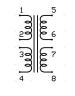
For the PP output transformer I don't use a gap. My EI laminations are fully interleaved in the stack with 1up - 1 down but could be groupled in twos or threes and that would be okay too if you have a ready made transformer.
Wit EI laminations one always gets a tiny gap, simply because of the mechanics of butting up the E and I sections.
I would recomend that you use the two output windings in parallel, which will give you 2:1 step down.
Note: 4:1 needs two sets of four windings, plus a lot of head scratching to get all the winding sections in their proper order - and yes, even I have to think about it when I wire up a new transformer for the first time 🙂
What size is your transformer?
Best wishes,
Susan.
Tyimo said:Some question about the OPT:
Is there any air gap?
If I have a Quad Filar wound OPT with similar windings (each winding = 155 mH ) how should I connect it 2:1 or 4:1 mode??
For the PP output transformer I don't use a gap. My EI laminations are fully interleaved in the stack with 1up - 1 down but could be groupled in twos or threes and that would be okay too if you have a ready made transformer.
Wit EI laminations one always gets a tiny gap, simply because of the mechanics of butting up the E and I sections.
I would recomend that you use the two output windings in parallel, which will give you 2:1 step down.
Note: 4:1 needs two sets of four windings, plus a lot of head scratching to get all the winding sections in their proper order - and yes, even I have to think about it when I wire up a new transformer for the first time 🙂
What size is your transformer?
Best wishes,
Susan.
Dear Susan,
please forgive my ignorance, but when it comes to transformers I`am a complete moron. What type of output transformer would you suggest for a pure ribbon, driven with your Zeus amp from 300 Hz up? The ribbon itself would be 1 meter tall (or more), with a impedance of some 0.2 ohms and the desired impedance would be 4 ohms.
Thanks,
Miro
Hi Susan!
Thanks for the help!
It was not clear to me because on your:
http://www.susan-parker.co.uk/zeus-original-irfp150-pics-fft-1khz.htm
you wrote 4:1 and on the 35W OPT Specification there is the simple quad filar wound OPT:
http://www.susan-parker.co.uk/zeus-out-tx.htm.
Greets:
Tyimo
Thanks for the help!
It was not clear to me because on your:
http://www.susan-parker.co.uk/zeus-original-irfp150-pics-fft-1khz.htm
you wrote 4:1 and on the 35W OPT Specification there is the simple quad filar wound OPT:
http://www.susan-parker.co.uk/zeus-out-tx.htm.
It will be made with a 200VA toroid core. It can handel 50Watts at 25Hz.What size is your transformer?
Greets:
Tyimo
Hi Tyimo,
Ah! If you look at:
http://www.audiophonics.com/audiophonics-zeus-out-tx.html
... version two, that is 4:1 step down and are as fitted to the amps.
I try to keep the original pages in place, but haven't done any audio updates on the susan-parker.co.uk for a long time. All new info is on the www.audiophonics.com website.
Once I have sorted out the line driver for them, my plan is to run my original Zeus35 amps in 4:1 mode with single driver JX92s speakers for rear channel 5.1 setup.
They still work as originally built in 1995. I haven't even had to adjuste the bias.
Best wishes,
Susan.
Tyimo said:It was not clear to me because on your:
http://www.susan-parker.co.uk/zeus-original-irfp150-pics-fft-1khz.htm
you wrote 4:1 and on the 35W OPT Specification there is the simple quad filar wound OPT:
http://www.susan-parker.co.uk/zeus-out-tx.htm.
Ah! If you look at:
http://www.audiophonics.com/audiophonics-zeus-out-tx.html
... version two, that is 4:1 step down and are as fitted to the amps.
I try to keep the original pages in place, but haven't done any audio updates on the susan-parker.co.uk for a long time. All new info is on the www.audiophonics.com website.
Once I have sorted out the line driver for them, my plan is to run my original Zeus35 amps in 4:1 mode with single driver JX92s speakers for rear channel 5.1 setup.
They still work as originally built in 1995. I haven't even had to adjuste the bias.
Best wishes,
Susan.
Output Transformer for Ribbon Speaker
Hi Miro,
Don't worry, we all are learning. I have been working on these amps now for over 15 years 🙂
For use in a Zeus amp system I would recomend winding a custom output transformer with multiple secondaries that can be connected in parallel. It would be a bit more work, but would provide the best soultion.
Impedance is the square of the turns, so you would be wanting something like a 16:1 step down.
Best wishes,
Susan.
Hi Miro,
fivestring said:please forgive my ignorance, but when it comes to transformers I`am a complete moron. What type of output transformer would you suggest for a pure ribbon, driven with your Zeus amp from 300 Hz up? The ribbon itself would be 1 meter tall (or more), with a impedance of some 0.2 ohms and the desired impedance would be 4 ohms.
Don't worry, we all are learning. I have been working on these amps now for over 15 years 🙂
For use in a Zeus amp system I would recomend winding a custom output transformer with multiple secondaries that can be connected in parallel. It would be a bit more work, but would provide the best soultion.
Impedance is the square of the turns, so you would be wanting something like a 16:1 step down.
Best wishes,
Susan.
Hi Susan!
Could you tell me how much is the DC resistance of your 35W quadfilar wound OPT windings?
Greets:
Tyimo
I see! Thank you!... version two, that is 4:1 step down and are as fitted to the amps.
Could you tell me how much is the DC resistance of your 35W quadfilar wound OPT windings?
Greets:
Tyimo
- Home
- Amplifiers
- Solid State
- Zero Feedback Impedance Amplifiers