Re: Bias supply
Thank you. It's actually more of a current feedback loop, but it does serve to prevent the current from rising as the temperature of the radiator rises. I'm kinda proud of it, as I don't have the training or experience to develop more complicated stuff.
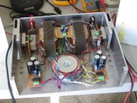
Here's a shot of the assembled amp - completed casework tomorrow.
Sheldon
Susan-Parker said:Thanks for the temperature compensating bias supply info.
Thank you. It's actually more of a current feedback loop, but it does serve to prevent the current from rising as the temperature of the radiator rises. I'm kinda proud of it, as I don't have the training or experience to develop more complicated stuff.
Here's a shot of the assembled amp - completed casework tomorrow.
Sheldon
Attachments

Ok, finally plugged it into the main system. I have it running the horn from about 1200Hz on up. Sounds very nice. Some more experiments on circuit variations to come (may have to make at least the appearance of progress on a few projects around the house first), but a few comments.
If you have a low impedance source, this is a great amp for high efficiency speakers. I had a little inductive hum when I put everything in the case and fired it up the first time. But by turning the power toroid some, that completely went away. No hum or noise whatsoever. You can stick your head inside the horn and hear nothing. This, with a very simple power supply. Also, no thump or click on power up or power off. And no chance of DC on your driver.
If you want to use it full range, you want to make sure that the input transformer has sufficient inductance, per Steve Eddy's comments earlier, to provide adequate input impedance for your source at those frequencies.
I haven't measured with a scope yet, but I calculate that I should be able to swing about 10Vpp (7Vrms) at the output, so about 6 watts into 8 ohms. Seems about right in my system, based on the output of my preamp.
My original plan was to drive this with a tube driver, and that's still on the table at some point. Drivers designed for something like a 300B should work well. Mine is a 6sn7 followed by an 801 and will swing about 200V, so I will use a 10:1 step down input transformer. Initial testing with 4:1 sounded promising. The experts will correct me if I'm wrong, but it should not be too difficult to get adequate inductance in the transformer to do low frequencies well too.
One question raised about the FET version is the high input capacitance. I'd be interested in a closer analysis of this, as I lack full understanding in this area. I'm not sure how to calculate what it is in this cascode configuration, but since the lower FET is kept at a constant Vds, the capacitance should remain constant. Brian Beck, over on the tube forum, has postulated that the change in input capacitance of Mosfets with Vgs can cause audible phase changes with amplitude in regular mosfet amplifier outputs. Sounds logical, but would be avoided here.
No coupling capacitors, so no potential cap colorations. Also no chance of overload recovery issues - at least in this stage.
All and all, a very cool concept by Susan. If you a looking to build something unique, consider trying one of these. I'm gonna make it easier for you too, if you want to build a low power version. The minumum order I could find for the EI 112 laminations was 1000 pcs, and the minimum order of 1" bobbins was 25pcs. It take only about 70 lams per transformer. So if you contact me offline, I can hook up a few builders with a couple sets, for the cost of postage. Oh, there's another cost as well. I'm not going through the effort to send this stuff out for pack rats. You have to publish your design and progress on this forum before I send stuff, and commit to soldering within a reasonable time.
Sheldon
Hi Sheldon,
Thanks for the update, pleased to hear that you have a working and listenable system.
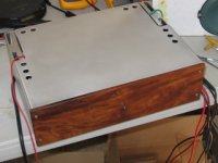
I like the wood front panel, very smart and a nice contrast to the normal acres of aluminium (which I admit to doing out of expediancy).
Best wishes,
Susan.
Thanks for the update, pleased to hear that you have a working and listenable system.
I like the wood front panel, very smart and a nice contrast to the normal acres of aluminium (which I admit to doing out of expediancy).
Best wishes,
Susan.
Susan-Parker said:pleased to hear that you have a working and listenable system.
Thanks, but I'd say it's a well more than listenable. 🙂
Sheldon
Despite my fractured syntax in the previous post, I'm mostly coherent and quite enjoying this little amp. Apologies to Susan for taking a perfectly fine design and fiddling with it. But I can't help myself in that regard. I won't get the chance for some additional fiddling for a while (anyway, time to listen for a bit), but that doesn't keep me from thinking about it. Wondering if one wanted more power from the jFET version if an easy approach wouldn't be to pick an appropriate npn BJT for the upper element in the cascode, with an extra diode or two from base to common to bias it? Everything else could remain the same.
Sheldon
Sheldon
> Wondering if one wanted more power from the jFET version if an easy approach wouldn't be to pick an appropriate npn BJT for the upper element in the cascode, with an extra diode or two from base to common to bias it?
If you were to cascode the JFET at something like 3V, you could happily bias it at 1.5A. (5W dissipation, See Zen V9). So the limit for bias in the current circuit is the cascode device.
To use a BJT, I guess you need to supply base current (as well as bias current for the diodes) from the top rail via a resistor or a constant current source. It then loses the simplicity of the self biasing of the cascode JFET. In that case you might as well use a MOSFET cascode, as in Zen V9, instead of a BJT.
Of course if you can find a large enough depletion MOSFET (in terms of Idss), or use multiple JFET in parallel as cascode, you might still be able to stick to the current self-biasing cascode circuit.
I, personally, would do it like Nelson did in ZV9, i.e using MOSFET as cascode.
Patrick
EUVL said:If you were to cascode the JFET at something like 3V, you could happily bias it at 1.5A. (5W dissipation, See Zen V9). So the limit for bias in the current circuit is the cascode device.
To use a BJT, I guess you need to supply base current (as well as bias current for the diodes) from the top rail via a resistor or a constant current source. It then loses the simplicity of the self biasing of the cascode JFET. In that case you might as well use a MOSFET cascode, as in Zen V9, instead of a BJT.
Of course if you can find a large enough depletion MOSFET (in terms of Idss), or use multiple JFET in parallel as cascode, you might still be able to stick to the current self-biasing cascode circuit.
I, personally, would do it like Nelson did in ZV9, i.e using MOSFET as cascode.
Patrick
Yes, it would require a separate bias supply, but it wouldn't be hard to use the same type of shunt supply I'm using for the FET. The only depletion mode MOSFET I could find easily, and that would come close would be this one: http://www.supertex.com/pdf/datasheets/DN2625.pdf But, to my untrained eye, the transfer characteristics look suspect for this application.
I've got some of Susan's matched FETs that should be fine if I want to go this route.
Sheldon
Do take a look at the article on Zen Version 9 on the Pass Forum.
Maybe the answer is already there.
For high current bias >1A, I myself am using 2SK1529 as cascode. But IRFP240 would be just fine.
Patrick
Maybe the answer is already there.
For high current bias >1A, I myself am using 2SK1529 as cascode. But IRFP240 would be just fine.
Patrick
EUVL said:Do take a look at the article on Zen Version 9 on the Pass Forum.
Maybe the answer is already there.
For high current bias >1A, I myself am using 2SK1529 as cascode. But IRFP240 would be just fine.
Patrick
Thanks for the coments Patrick,
Yes, I have looked at the Z9. Even though this amp does no voltage amplification via the cascode, I think the schema biasing the MOSFET should work with some modifications. As I wouldn't use the top part of the power supply, some way of filtering the raw B+ would be needed. Or could use a small separate supply. But, as this is partly a mental exercise, how about something like this?
Would probably need two LED in series to get the bias voltage needed, or maybe an LED and some diodes.
Sheldon
Attachments
Nelson Pass said:Are you matching those JFETs?
😎
Thanks for looking in Nelson,
I bought them matched via Grey's group buy thread. At 0.4A bias per device, I'm unbalanced by a mA or so in one channel, and about 7mA on the other. With the small air gap (0.1mm) in the transformer, I think that should be pretty good.
Sheldon
> But, as this is partly a mental exercise, how about something like this? Would probably need two LED in series to get the bias voltage needed, or maybe an LED and some diodes.
Looks OK.
There was a post some time ago on noise measurements of LEDs vs Zener diodes. And the zeners were surprisingly good. Since then I do not bother with LEDs anymore. Just current source, Zener, with a 100uF cap across.
> Are you matching those JFETs?
Grey has only been selling matched LU1014s for quite some time. For my own use, I measure and match them again within a batch of 20 "matched" devices, etc.
Patrick
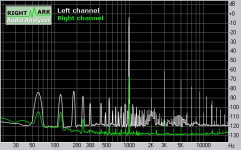
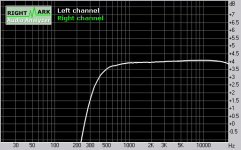
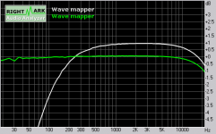
Just for completeness, the frequency response driven by the PP amp:
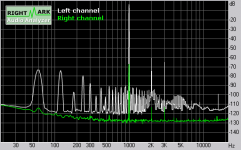
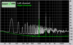
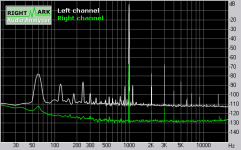
What is evident from these quicky tests, is that the Zeus is highly dependent on the driver and transformers. You can see that the distortion is high when driven by the soundcard alone (M Audio Transit). But when driven by an amplifier with presumably much lower impedance, the distortion profile essentially matches that of the amplifier alone. So the Zeus itself, as Susan has stated, will reflect the character of the driver. I didn't test it with my preamp, as I didn't want to drag it out of the system, but I would expect it to give low distortion as it has an output impedance of 75R.
The frequency response is a function of the input transformer, as you can see by comparing the response of the soundcard driven Zeus vs. the pp amp driven Zeus. Note that the response at the high end is good. The slight additional roll off at 20kHz of the PP amp driver reflects the response of it's OPT's. For my present use as a tweeter amplifier, the roll off at lower frequencies is fine. But if it were to be full range, a different input/splitter transformer would be in order.
Note: white is the Zeus/pp response, green is the pp response
Attachments
Tribute to Zeus
Yesterday I read through most of this thread.
Susan Parker's Zeus is the most interesting and important amplifier I have seen for a long time.
Why such a statement? Some reasons:
Yesterday I read through most of this thread.
Susan Parker's Zeus is the most interesting and important amplifier I have seen for a long time.
Why such a statement? Some reasons:
- THD is so small that it is far below audible level. Practically all commercial amplifiers nowadays fortunately fall into this category. Anyway THD is important, and that is why I listed it here, but its importance is often exaggerated to ridiculous levels. Of all different distortions Harmonic Distortion is one of the most natural.
- Zeus is a very fast amplifier. That leads to the great accuracy and exact phase response into high ultrasound frequencies.
- Without feedback the amplifier should be totally free of Transient Intermodulation Distortion. Lack of this kind of "unnatural" distortion allows the listener enjoy music without suffering subconsciously of the distortion.
- Noise is so low that it is practically non-existent. Usually people tolerate some noise that their audio equipment generates, but in this case there is no reason to learn any tolerance. The lack of noise makes listening even more natural experience.
- One can expect long life for the Zeus amplifier, since all components are robust, especially transformers. The two semiconductors of the amplifier are power MOSFETs.
- Zeus is not a perfect amplifier. There may be some small crossover distortion left. I am not worried about it.
[/list=1]
There are some reasons to carefully think over whether some further improvements would improve or degrade the sound. I don't mean to suggest that a struggle for developing this particular amplifier would be futile. Just think what is advantageous and what is not.
- Home
- Amplifiers
- Solid State
- Zero Feedback Impedance Amplifiers