Re: Lovoltech devices
I may take back what I said about the devices being fried. It gets weirder. After reading your message, I got to thinking about the Zen application and Zen's are a bit different. They pass current well up in this range, with 47K resistance to ground at the gate. So if there were the gate current I'm seeing it couldn't work. But, both the Zen, and Patrick's headphone amp are cascoded and the Lovoltech opperates at lower voltage.
So, I tried a 7V supply. Guess what? The current at the gate is much lower. With 1.5 ohms on the output and 47k on the gate, I tried two different power supplies. With the 11V unit I measured 9.2V (obviously sagging with the current) at the drain, 4.1V at the source and 2.8V at the gate. With the lower voltage transformer, I got 7V drain, 2.3 source, and .9V gate. Taking out the 47k gate resistor I got 11.3V drain, and 1.8V source for the 11V unit, and 7.84 drain and 1.5V source for the 7Volt unit (gate grounded in both cases).
I had been convinced that I may have toasted the FET's but this seems strange. I didn't try this test with all the FET's, only a couple. But in my other tests, their behavior was identical, which makes me wonder if they have failed. Seems strange that they would all suffer partial failure to the exact same degree.
I ordered a few more test.
Another quick question on the winding Susan. I note that you begin and end the windings on the same side of the bobbin. I assumed that this was for convenience of making the various connections. Is that the case, or does it have any performance related effect?
Sheldon
Susan-Parker said:I remain puzzled by the Lovoltech device's behavior.
I also haven't had any reply from my email asking for clarification (will let you know if I hear anything).
I would go with Patrick's possibility of gate damage, but the normal use turn on current is something that to me seems to indicate that there may be something else going on.
And Mr Nelson Pass's Zen 8 & 9 variation circuits use the LU1014D as a gain stage, so the operation is different to her
I may take back what I said about the devices being fried. It gets weirder. After reading your message, I got to thinking about the Zen application and Zen's are a bit different. They pass current well up in this range, with 47K resistance to ground at the gate. So if there were the gate current I'm seeing it couldn't work. But, both the Zen, and Patrick's headphone amp are cascoded and the Lovoltech opperates at lower voltage.
So, I tried a 7V supply. Guess what? The current at the gate is much lower. With 1.5 ohms on the output and 47k on the gate, I tried two different power supplies. With the 11V unit I measured 9.2V (obviously sagging with the current) at the drain, 4.1V at the source and 2.8V at the gate. With the lower voltage transformer, I got 7V drain, 2.3 source, and .9V gate. Taking out the 47k gate resistor I got 11.3V drain, and 1.8V source for the 11V unit, and 7.84 drain and 1.5V source for the 7Volt unit (gate grounded in both cases).
I had been convinced that I may have toasted the FET's but this seems strange. I didn't try this test with all the FET's, only a couple. But in my other tests, their behavior was identical, which makes me wonder if they have failed. Seems strange that they would all suffer partial failure to the exact same degree.
I ordered a few more test.
Another quick question on the winding Susan. I note that you begin and end the windings on the same side of the bobbin. I assumed that this was for convenience of making the various connections. Is that the case, or does it have any performance related effect?
Sheldon
So, just another thought. I looked around at some of the designs here that employ the Lovoltech device. Seems that most (all that I found) are using it in a cascode with 3Vds, or less. Note that going from about 9 Vds to about 7Vds, the strange gate current dropped by a factor 3. I'm guessing is would be a non-issue at a Vds of 3V. I'll try it tomorrow.
Sheldon
Sheldon
Sheldon, Susan,
If I am correct, the reason why the LU1014 is cascoded by Nelson (I just copied) is to :
a) reduce dissipation to a level that the device will work with acceptable reliability;
b) reduce input capacitance (which is large even compared to MOSFETs).
Point (b) is the main reason why I cascode for my application (200mA) as dissipation should not be a big issue.
To operate the LU1014 in triode mode, you need to go down to Vgs around -1V. The exact load resistance / Vgs / Vds combination you need to experiment with, and it varies from FET to FET a bit.
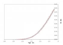
I doubt that your gate current has to do with Vds alone. If you look at Fig.5 of the datasheet, you would notice that you only get gate current in mA's if you forward bias the gate to Vgs > 0.6V, as one would expect.
The reason why the datasheet shows gate currents up to 30mA is that in their original application (i.e. switching), you DO want to forward bias the gate.
Please try to measure a new, undamaged device with a large gate resistor (say 1k) and low Vds (say 3V), starting with -2V Vgs and NOT in your circuit (just to eliminate unknown problems). Increase Vgs slowly to increase current. And you can measure the voltage across the gate resistor to see whether there are gate currents. It does not take so much time, and will answer a lot of questions.
Attached a measurement with Vds at 12V, with a 1R source resistor and a 4R drain resistor (to simulate the load in a possible application). Just to show the device works without problems at 12V. Gate resistor was 1k.
Patrick
If I am correct, the reason why the LU1014 is cascoded by Nelson (I just copied) is to :
a) reduce dissipation to a level that the device will work with acceptable reliability;
b) reduce input capacitance (which is large even compared to MOSFETs).
Point (b) is the main reason why I cascode for my application (200mA) as dissipation should not be a big issue.
To operate the LU1014 in triode mode, you need to go down to Vgs around -1V. The exact load resistance / Vgs / Vds combination you need to experiment with, and it varies from FET to FET a bit.
I doubt that your gate current has to do with Vds alone. If you look at Fig.5 of the datasheet, you would notice that you only get gate current in mA's if you forward bias the gate to Vgs > 0.6V, as one would expect.
The reason why the datasheet shows gate currents up to 30mA is that in their original application (i.e. switching), you DO want to forward bias the gate.
Please try to measure a new, undamaged device with a large gate resistor (say 1k) and low Vds (say 3V), starting with -2V Vgs and NOT in your circuit (just to eliminate unknown problems). Increase Vgs slowly to increase current. And you can measure the voltage across the gate resistor to see whether there are gate currents. It does not take so much time, and will answer a lot of questions.
Attached a measurement with Vds at 12V, with a 1R source resistor and a 4R drain resistor (to simulate the load in a possible application). Just to show the device works without problems at 12V. Gate resistor was 1k.
Patrick
Attachments
Transformer winding
Hi Sheldon,
It's purly mechanical, so that when the transformer is assembled all the wires come out on one shroud which can then be faced to the rear of the chassis.
Best wishes,
Susan.
Hi Sheldon,
Sheldon said:Another quick question on the winding Susan. I note that you begin and end the windings on the same side of the bobbin. I assumed that this was for convenience of making the various connections. Is that the case, or does it have any performance related effect?
It's purly mechanical, so that when the transformer is assembled all the wires come out on one shroud which can then be faced to the rear of the chassis.
An externally hosted image should be here but it was not working when we last tested it.
Best wishes,
Susan.
EUVL said:Sheldon, Susan,
If I am correct, the reason why the LU1014 is cascoded by Nelson (I just copied) is to :
a) reduce dissipation to a level that the device will work with acceptable reliability;
b) reduce input capacitance (which is large even compared to MOSFETs).
Point (b) is the main reason why I cascode for my application (200mA) as dissipation should not be a big issue.
To operate the LU1014 in triode mode, you need to go down to Vgs around -1V. The exact load resistance / Vgs / Vds combination you need to experiment with, and it varies from FET to FET a bit.
I doubt that your gate current has to do with Vds alone. If you look at Fig.5 of the datasheet, you would notice that you only get gate current in mA's if you forward bias the gate to Vgs > 0.6V, as one would expect.
The reason why the datasheet shows gate currents up to 30mA is that in their original application (i.e. switching), you DO want to forward bias the gate.
Please try to measure a new, undamaged device with a large gate resistor (say 1k) and low Vds (say 3V), starting with -2V Vgs and NOT in your circuit (just to eliminate unknown problems). Increase Vgs slowly to increase current. And you can measure the voltage across the gate resistor to see whether there are gate currents. It does not take so much time, and will answer a lot of questions.
Attached a measurement with Vds at 12V, with a 1R source resistor and a 4R drain resistor (to simulate the load in a possible application). Just to show the device works without problems at 12V. Gate resistor was 1k.
Patrick
Patrick, the current I'm measuring in not forward gate current. It is reverse gate current, and it's less than 1mA. I had already planned to do the measurements as you suggest, and will do some later today. The measurements I reported on in the previous post were made as you suggested, with only the device, a source resistor, and a gate resistor as noted. Actually, the graph you show agrees quite well with my measured results at 11V. The gate current of around 0.5mA would not be much of an issue with a 1K gate resistor and a low impedance source.
More to follow.
Sheldon
Re: Zeus Zero Feedback Impedance Amplifier Output Transformer
Surf was calling earlier, but I came back and measured at 3.8Vds, 1.5R on source, 47k on gate. Results: Source 1.15V, 2mV across gate resistor (or 40nA). I think my FET's are OK and this is just how they behave.
So, if we want to have a simple single device mini Zeus, then it has to be resistively loaded at the transformer output center tap to ground. There will be some current from the gates through the input secondaries, and that should be checked for balance. At 13V maximum rail, the swing will be about +/-10V, after subtracting the bias voltage and drop at the gate. With a 2:1 step down, that should give about 7Vrms output, or about 6W into 8Ohms. As Susan said, with this type of loading, the amp should be biased into class A, which will be a minimum of about 0.6A per device. I would think that if it's biased into class A, that one could use a constant current source instead of a bias resistor, but the heat dissipation would be the same.
I think that the problems I had with trying a negative bias supply through the input secondaries, have to do with the current at the gate fluctuating and interacting with the inductance of the secondary. I would guess that with no current, as in the low voltage case, this should not be a problem. If that's the case, and the FET is cascoded with a higher voltage mosfet, then the amp doesn't have to be biased in class A. And, of course, the supply rail is not limited by the Lovoltech device. Patrick, I would think that the choice of Mosfet is not too critical, nor would they need to be carefully matched, as long as the jFet's are matched?
Looks like you've got it.
Sheldon
EUVL said:I doubt that your gate current has to do with Vds alone. If you look at Fig.5 of the datasheet, you would notice that you only get gate current in mA's if you forward bias the gate to Vgs > 0.6V, as one would expect.
The reason why the datasheet shows gate currents up to 30mA is that in their original application (i.e. switching), you DO want to forward bias the gate.
Please try to measure a new, undamaged device with a large gate resistor (say 1k) and low Vds (say 3V), starting with -2V Vgs and NOT in your circuit (just to eliminate unknown problems). Increase Vgs slowly to increase current. And you can measure the voltage across the gate resistor to see whether there are gate currents. It does not take so much time, and will answer a lot of questions.
Attached a measurement with Vds at 12V, with a 1R source resistor and a 4R drain resistor (to simulate the load in a possible application). Just to show the device works without problems at 12V. Gate resistor was 1k.
Patrick
Surf was calling earlier, but I came back and measured at 3.8Vds, 1.5R on source, 47k on gate. Results: Source 1.15V, 2mV across gate resistor (or 40nA). I think my FET's are OK and this is just how they behave.
So, if we want to have a simple single device mini Zeus, then it has to be resistively loaded at the transformer output center tap to ground. There will be some current from the gates through the input secondaries, and that should be checked for balance. At 13V maximum rail, the swing will be about +/-10V, after subtracting the bias voltage and drop at the gate. With a 2:1 step down, that should give about 7Vrms output, or about 6W into 8Ohms. As Susan said, with this type of loading, the amp should be biased into class A, which will be a minimum of about 0.6A per device. I would think that if it's biased into class A, that one could use a constant current source instead of a bias resistor, but the heat dissipation would be the same.
I think that the problems I had with trying a negative bias supply through the input secondaries, have to do with the current at the gate fluctuating and interacting with the inductance of the secondary. I would guess that with no current, as in the low voltage case, this should not be a problem. If that's the case, and the FET is cascoded with a higher voltage mosfet, then the amp doesn't have to be biased in class A. And, of course, the supply rail is not limited by the Lovoltech device. Patrick, I would think that the choice of Mosfet is not too critical, nor would they need to be carefully matched, as long as the jFet's are matched?
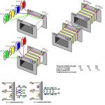
bokakob said:I made a new picture for the output transformer. Perhaps someone who can, would correct it.
Looks like you've got it.
Sheldon
> Patrick, I would think that the choice of Mosfet is not too critical, nor would they need to be carefully matched, as long as the jFet's are matched?
That is not quite true.
The cascode MOSFET has limited transconductance, so it acts almost like a drain resistor (the gate of the cascode is at constant voltage, but the source voltage varies a bit with current, dependent on the transcoductance of the cascode MOSFET). So the transconductance of the cascode affects Vds of the LU1014, and hence, together with the source resistor, its triode loadline.
You need to experiment with cascode voltage and MOSFET types to get the best linearity at a certain bias current. I would suggest using IRFP240 or 2SK1529 for anything around 1A, and IRF610 for anything less than 0.5A. Then you should make the measurements with the actual cascode, and change your loadline by varying the cascode gate voltage.
In any case, I shall match them as well.
Of course you can save all this trouble by going back to a single MOSFET. 🙂
Patrick
EUVL said:[BThe cascode MOSFET has limited transconductance, so it acts almost like a drain resistor (the gate of the cascode is at constant voltage, but the source voltage varies a bit with current, dependent on the transcoductance of the cascode MOSFET). So the transconductance of the cascode affects Vds of the LU1014, and hence, together with the source resistor, its triode loadline.
In any case, I shall match them as well.
[/B]
Point Taken
EUVL said:[BOf course you can save all this trouble by going back to a single MOSFET. 🙂
[/B]
You're not seriously suggesting that we be practical are you? 😀
Since I already have the matched FET's how bout this for a low power version? The partial schematic shows approximate voltages for the cascode at quiescent conditions. We can swing a maximum of about 11V here.
Sheldon
Attachments
> Since I already have the matched FET's how bout this for a low power version?
Save your LU1014s. IRFP240 only costs US$1.xx each.
If you have to do it like that, then at least parallel 2 matched LU1014s for the cascode.
a) You lower the dissipation for each JFET at the cascode.
b) By halving the current of the cascode and hence putting its gate voltage more negative, you get a higher Vds across the driver JFET.
Patrick
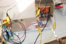
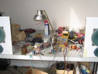
Well, this may not be the best of all possible ways to do this, but it works. Sounds pretty good too - at least as far as I can tell with a single channel driven from a cheap portable CD Player. With no signel, it's as quiet as a grave. Ear right on 96dB speaker, no hum, no buzz, no nuthin. I'm going to go ahead and build it up. The way I do the case will allow me to easily sub out the entire output block, so I can easily try different topologies.
Shown with current operating conditions. The resistance of the transformer windings are 0.10R each - measured with a battery and 100R resistor as a current source.
Sheldon
Shown with current operating conditions. The resistance of the transformer windings are 0.10R each - measured with a battery and 100R resistor as a current source.
Sheldon
Attachments
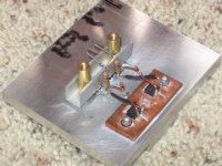
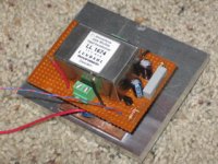
Here's a picture of the amp. The input FET's are under the aluminum bar clamp, shown above the copper bar. The transistors soldered (with Tix solder) to the copper bar are the top cascode FET's, as they will need the better heat sinking. The little perf board on the top left hides the input transformer underneath. The main power supply module is in the lower left. The bias supply is a simple CRC supply fed by a few extra windings on the main transformer, per Susan's suggestion.
Sheldon
Sheldon
Attachments
Hi Sheldon,
Thanks for the updates.
In my book "the best way" is the way that works for you and that you are happy with.
Pleasing that you are getting good results.
Um, that seems a little low to me.
Easiest way to get the approximate winding resistance is to calculate based on wire length.
c. 150 turns of 0.8mm wire on a EI-112 square bobbin.
Bobbin 2.22" sq. with 1.16" sq. center, height 1.65".
See www.plastron.net/Images/CatalogP083-4.jpg for drawing.
Wire aperture 1.56" x 0.976" max.
Wire mean length of c. 7.0" (for max fill), = 175mm per turn.
150 turns = 26.822 meters.
0.8mm wire is 35.35 ohms / 1000 meters.
DC resistance = c. 0.95 ohms
So I would guess you are measuring about 1 ohm.
Best wishes,
Susan.
Thanks for the updates.
Sheldon said:Well, this may not be the best of all possible ways to do this, but it works. Sounds pretty good too - at least as far as I can tell with a single channel driven from a cheap portable CD Player. With no signel, it's as quiet as a grave. Ear right on 96dB speaker, no hum, no buzz, no nuthin. I'm going to go ahead and build it up. The way I do the case will allow me to easily sub out the entire output block, so I can easily try different topologies.
In my book "the best way" is the way that works for you and that you are happy with.
Pleasing that you are getting good results.
Shown with current operating conditions. The resistance of the transformer windings are 0.10R each - measured with a battery and 100R resistor as a current source.
Um, that seems a little low to me.
Easiest way to get the approximate winding resistance is to calculate based on wire length.
c. 150 turns of 0.8mm wire on a EI-112 square bobbin.
Bobbin 2.22" sq. with 1.16" sq. center, height 1.65".
See www.plastron.net/Images/CatalogP083-4.jpg for drawing.
Wire aperture 1.56" x 0.976" max.
Wire mean length of c. 7.0" (for max fill), = 175mm per turn.
150 turns = 26.822 meters.
0.8mm wire is 35.35 ohms / 1000 meters.
DC resistance = c. 0.95 ohms
So I would guess you are measuring about 1 ohm.
Best wishes,
Susan.
Susan-Parker said:
Pleasing that you are getting good results.
Thank you for this elegant little amp. I plan to have some more fun with it. Will post along the way.
Susan-Parker said:Um, that seems a little low to me. (winding resistance)
So I would guess you are measuring about 1 ohm.
And dang those pesky little decimal points. They just jump around all over the place. I was doing a quick calc. before posting and one of them jumped. Didn't do the sanity check, as I should have. But you are, of course, correct.
Sheldon
That's really great. I haven't read the whole thread, so forgive
me for asking, why did you include 3 volt Zeners, and how did
you choose the 200 ohm Gate resistors?
😎
me for asking, why did you include 3 volt Zeners, and how did
you choose the 200 ohm Gate resistors?
😎
Nelson Pass said:That's really great. I haven't read the whole thread, so forgive
me for asking, why did you include 3 volt Zeners, and how did
you choose the 200 ohm Gate resistors?
😎
Thanks for the response.
The zeners were supposed to provide some protection against killing the FET with too much voltage swing. I actually just removed them, as they conduct enough to upset the bias a bit.
As for 200 ohm, well, I had them. Basically just a WAG. If you've got a preferred value, I'm willing and able to incorporate it.
Sheldon
Sheldon said:If you've got a preferred value, I'm willing and able to incorporate it.
I don't, I just wondered if you had optimized it.
😎
- Home
- Amplifiers
- Solid State
- Zero Feedback Impedance Amplifiers